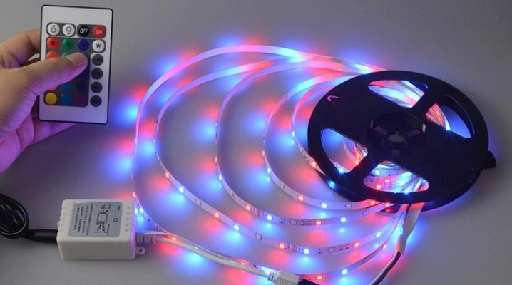
How to connect LED strip?
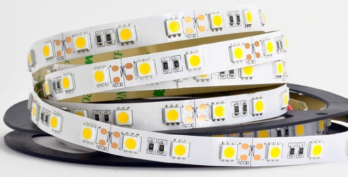
LED strips have become part of the everyday life and work environment of almost all people. They hold the leading position in light output and energy efficiency, bypassing even fluorescent lighting. The final contribution to their distribution was made by environmental safety for humans and the environment.
General rules
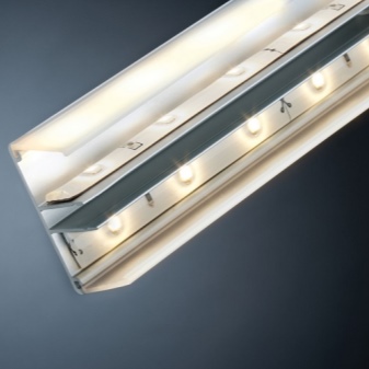
The LED strip, if it consists of parallel sections, and not of dozens of LEDs connected in series, should receive power supply with a voltage of 12 or 24 volts. Parallel connection of single LEDs on one bus of two wires (conductors) is allowed, but no more than several dozen pieces on each section. The power supply of such an assembly is no more than 3.3 V.
Remember the main rule: each LED should not receive more than 3.3 V (supply voltage), otherwise it will start to noticeably heat up... Heating to a temperature of more than 60 degrees leads to a rapid loss of glow brightness. An LED is not an incandescent lamp or a gas-discharge device: ideally, it should not heat up above 40 degrees.
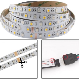
LED strip assembled from sections connected one through the other should not be longer than 15 meters... After 13 meters, as practice shows, the segments farthest from the power supply lose their brightness, this feature is associated with the limited thickness of the current-carrying paths. This requires connecting additional power supplies between spans of this length.
And the point here is not the defectiveness of the products: when the load is exceeded (in terms of power and current strength), the conductors heat up, their burnout is possible. To avoid this annoying misunderstanding, users go to extreme measures - they transfer the power line to an increased value of electrical voltage: 36, 48, 60, 72 and 84 V. In some cases, it is possible to switch to the standard 220.
Connecting large sequential groups, each of which consists of two assemblies of 80 absolutely identical (from the same batch) LEDs, in pairs in counter-parallel, allows you to solve the problem of power losses on wires, drivers and power supplies. The disadvantage is flicker with a frequency of 50 hertz, which at night, with a long (up to several hours) stay in such a room, spoils vision.
In the USA, where the mains frequency is not 50, but 60 Hz, flickering is not as felt and perceived as at fifty hertz, but it also leads to some fatigue of the eyes and brain of the user. Removing ripple allows an additional primitive adapter consisting of a network rectifier (4 high-voltage diodes connected in a bridge circuit and designed for a power of one hundred watts, and a polarized capacitor connected in parallel at the output).
The assembly is rated for 400 V - almost double the headroom for 220.
How to install with power supply?
Correctly connecting the diode assembly with the power supply, adhering to the circuit, is only half the battle. Installation of LED lighting is an additional calculation of the power and length of the supply cable.
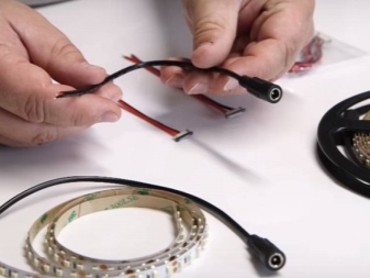
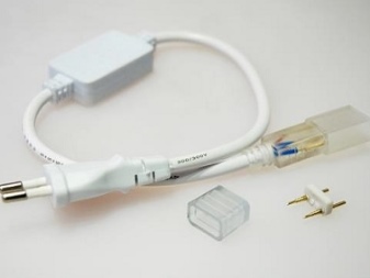
Assembling the cable
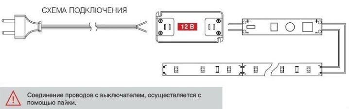
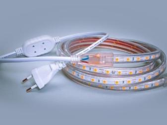
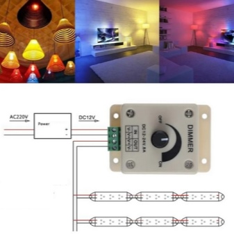
In most cases, the cable itself does not need to be assembled. These are two power conductors isolated from each other, through which the mains alternating voltage is supplied to the power supply.The 220-volt input is connected to it, a plug for the socket is placed at the other end of the cable, or an automatic fuse-switch is connected to a break in the line that goes directly to the switching panel.
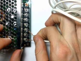
The output of the power supply using a short section of the same cable (the load on the power supply is also decent and commensurate here) is fed to the input of the first section of the light tape.
Connection to the unit
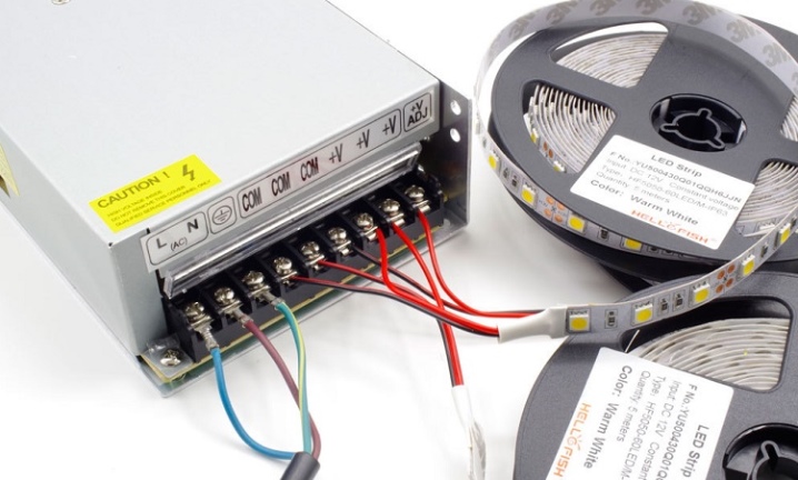
12 or 24 volt power supply - containing a transformer module. The transformer is necessary for galvanic isolation, without which the line where the LED assemblies are connected would be considered conditionally dangerous: even a voltage drop to zero volts at the output of a transformerless power supply would lead to a very painful electric shock.
It is important not to mix up the circuit so that the input and output of the power supply are swapped. Otherwise, a short circuit will occur (the automatic fuse will cut off the line), and the power supply will immediately burn out. The fact is that the main elements - a mains rectifier, a frequency converter, an HF transformer and an end rectifier with a stabilizer - are located in the power supply circuit diagram in this way - and not vice versa, a connection error is unforgivable.
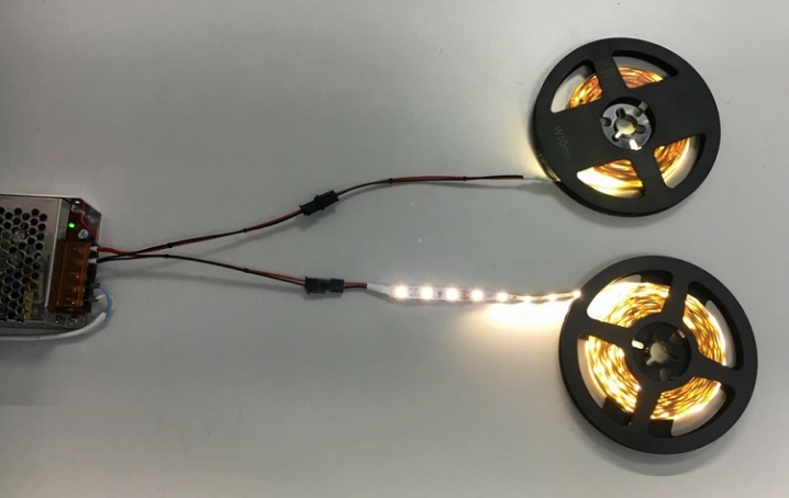
Test
In the simplest case, the LED assembly should glow brightly. If the permissible output power of the power supply does not match with the consumed light strip, it will shine weakly, and the power supply unit will overheat.... For example, if 3 ten-watt light strips are used, then it is advisable to choose a power supply with a power not of 30 W ("back to back", "peak", "maximum"), but give at least a double margin - about 60 watts delivered to the load. This will prevent it from overheating - and will preserve it a long, long service life.
Integration of the switch into the cord
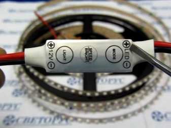
Switches for low-voltage assemblies are industrially produced, resembling an improved toggle switch, which is easier to turn on and off (with a certain amount of effort) than its earlier counterparts, released, for example, in the Soviet era.
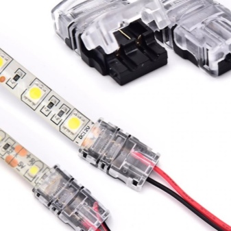
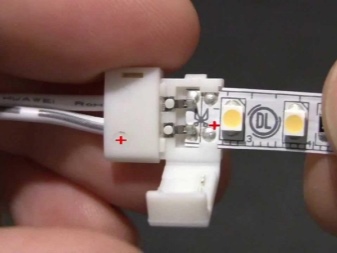
A switch in the form of a push-button, one pressing of which closes the circuit, the second opens (and so on, the cycle of use is repeated), you can hang it in the break of the cord and fix it on it. For convenience, in the most significant places, the circuit is made in the form of a detachable assembly - on connectors.
Stationary switches are no different from ordinary room switches - they switch the electrical circuit at the input, and not at the output of the power supply. They complement the automatic fuse - but do not replace it: safety rules must always be observed.
Repeated test
After completing the circuit with an additional switch, turn on the assembly again. It is difficult to make a mistake when connecting the cable - the switch is just a switched circuit break, there is nothing to burn out in it, except for the closing contacts. The switch is not an automatic device: in case of a serious short circuit, it often burns out (contacts burn out), only replacing it with a similar one or exactly the same helps.
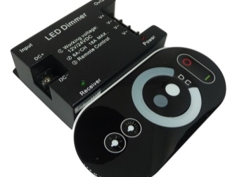
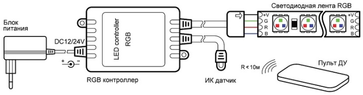
Installation diagram with dimmer
The dimmer adapter is not just a network electric driver that converts all the same 220 volts into 12 ... 80 volts necessary for power supply, but an additional unit in which power switching at several outputs is carried out using a microcontroller that controls small-sized relay modules or power transistor switches. Since transistor switching is much more durable than a relay unit (microscopic sparking is possible between the relay contacts, and they burn out after several million operations), in recent years it is she who displaces relay control.
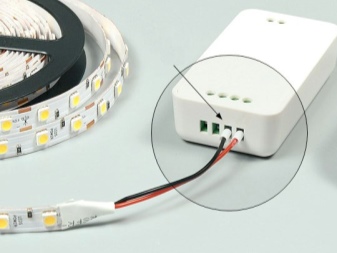
The dimmer is connected not directly to the network, but after the power supply. The exception is "smart sockets", in which control, similar to dimmer, is performed using cyclically connected and disconnected sockets. The second option is that the dimmer microcontroller is built into the power supply unit itself, but the general principle here remains unchanged: it is the output voltage, not the input voltage, that is switched by the dimmer module. The dimmer microcontroller receives power from all the same, for example, standard 12 volts.
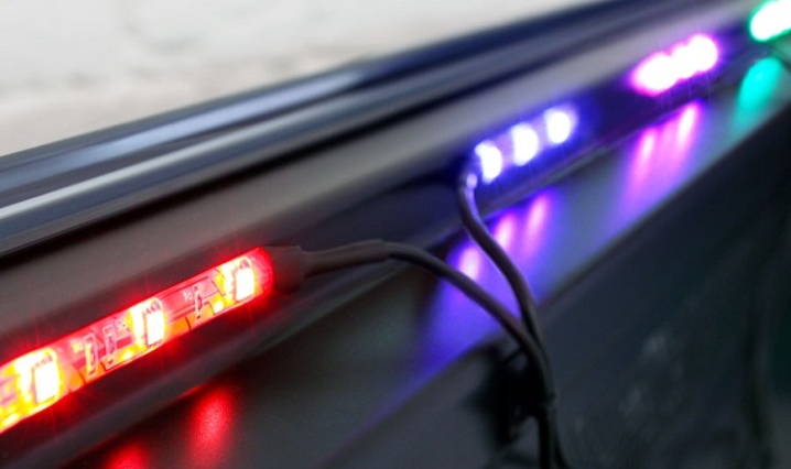
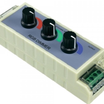
Dimmer lighting is designed for one-, two-, three- and four-color light strips. The last two options are red, blue and green light-emitting diodes (RGB tape), as well as white (RGBW light collection) can be added as the fourth. In special cases, ultraviolet and / or infrared LEDs are used for the main light strip emitting visible light of different colors. UV LEDs are the prerogative of, for example, disco clubs (visitors come in luminescent clothing that glows in ultraviolet light).
IR is used in guarded objects and restricted areas, whose video cameras perceive this light well. UV can also flicker (the program is set by turning on the corresponding dimmer mode), slowly extinguish and flash. Power supply for IR is often made switched on by the motion sensor of a video camera - or working continuously: It makes no sense to switch IR LEDs with a dimmer operating in a forced-set mode.
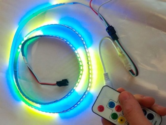
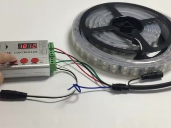
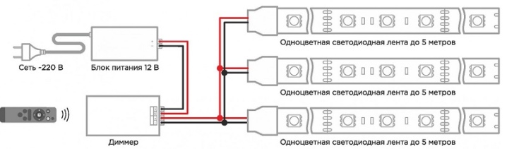
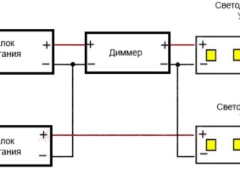
To connect the dimmer to the light strip electrical circuit, do the following:
- connect the network cable to the power supply (220 V input), using a general switch and / or automatic fuse;
- connect the output cable (12V) to the input of the dimmer block;
- connect dimmer control outputs to the corresponding "colored" tires at the entrance of the light strip.
The assembly is ready, test it. Complicated, branched networks, where more than one power supply unit is used, more than one dimmer, are configured independently, in the same or different modes.
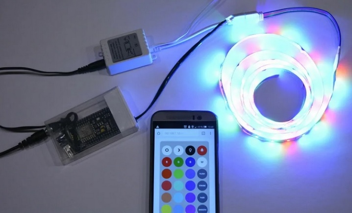
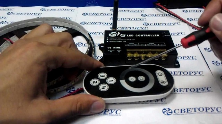
In addition, the dimmer can contain a receiver for an IR or radio remote control (as a rule, Nano or Bluetooth switching), and the control panel itself is supplied in the kit. Experienced homemade users manually assemble a dimmer control system, plus this method - freedom in choosing a glow mode, a light strip's operating schedule, the ability to control it remotely, via the Internet, etc.
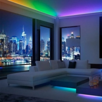
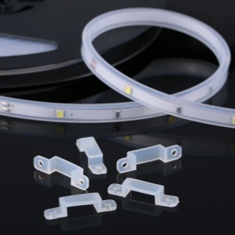
The scope is varied: country or country house, apartment, trading floor. And when using waterproof light strips filled with silicone (class IP-69), - a pool or dressing room in a bath or sauna, outdoor lighting of a radio mast or TV tower, illumination of billboards or signboards.
Dimmer lighting is a visual and very effective way to advertise your establishment or retail outlet.
Computer-Powered Installation
The LED assembly is powered mainly from 3 volts, when the LEDs are white, red, green, blue and other LEDs - on average from 2 volts. The USB port of a PC or laptop will supply 5 V, with a current of no more than half an ampere. This means that, guided by the power reserve rule, the light strip should not consume more than 300 milliamperes. To reduce the supply voltage, the following techniques are used:
- serial connection of color LEDs in pairs, with parallel connection of these pairs;
- parallel connection of white LEDs through lowering low-voltage switching stabilizers, damping diodes (but not resistors - they take significant power for their heating due to a voltage drop when the load is on).

The fact is that from 5 volts, white LEDs will simply burn out. A voltage of up to 3.3 is acceptable for them, at a higher one, they heat up significantly due to the strength of the current passing through them, which exceeds the operating rating specified in the passport data of a particular brand and model of the light element. Turn them on in series (we get a voltage of 2.5 V for each) - they barely glow and practically do not give light.
To do this, you need to lower the power supply from 5 to 3 V, using conventional rectifier diodes, connected in a chain, or using the so-called.DC-DC converters (inverters), converting, for example, a voltage of 5 ... 20 volts to 1.5 ... 4.2, while the output is set by a regulator (variable resistor), according to the resistance of which the board's microcontroller (converter) sets the required value. You can adjust the output voltage to 2 or 3 volts using a flat screwdriver. Users order converters such as the light strips themselves from Chinese retail chains - online.
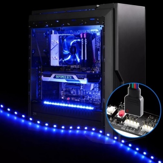
If in a PC or laptop there are 3.3 V voltage pickup points (this power is used in the latest generations of processors), then it is permissible to remove a couple of wires from this place by drilling additional holes in the right place of the case. Here you need a good knowledge of how the laptop is arranged - so as not to accidentally disable it by inept actions and unacceptable load of the power adapter by current. Other voltages can be taken from the case of the system unit (built-in power supply unit): 5, 9, 12, 15, 19, 21 volts - be guided by what you need, but do not overload your power supply in terms of power and current.
In some cases, when the task is to create both the main and emergency lighting in the same design, a corresponding battery (or a battery of such batteries) is connected to the power supply unit.
In some situations, such a battery can be a built-in laptop battery or an uninterruptible power supply; no unnecessary components are visible, since the battery in both cases is mounted inside the PC by the manufacturer.

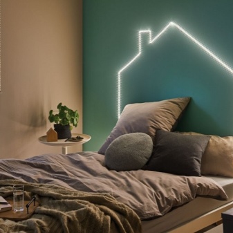
How to securely fasten?
In the room, the LED strip can be glued to the wallpaper. Do-it-yourself fastening of the PSU already implies the use of additional fasteners. The PSU can be mounted on a wall made of any material (from wood to drywall), in the corners it can be hidden in a niche: a contrasting case (dark blue, for example, against a whitish background of the wall) can ruin the whole view in the room. In the corners, the power supply is usually located next to the PC system unit, behind the side of the table, it can be installed directly below, under the table top.
It is not recommended to glue something on the stretch ceiling, it is not recommended to attach it - the tape can peel off from the plastic under its own weight. In the worst cases, the stretch ceiling film itself is stretched, and it loses its even and neat appearance. In an office environment, the cable connecting the power supply unit to the power grid can be installed in steel (thick-walled) floor boxes, together with other power lines supplying employees' computers, laid in wall boxes running in the corners, next to the floor or under the very ceiling.
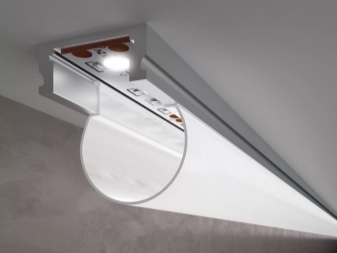
The most beautiful - and laconic - use of hidden gutters, as well as a homemade niche (in the thick outer wall of the building), to remove not only the wiring, but also the power supply itself. Outside, all hidden elements, except for the tape and the switch, are not visible. Attaching an LED strip to metal is one of the most reliable and durable methods. In the walls, unless you work in an electrical measuring laboratory or an X-ray office of a polyclinic or hospital, tightly fenced off from the rest of the building, it is difficult to find a metal base.
But any furniture can become such a basis - for example, metal guides are sometimes found on hanging cabinets. The tape glued to such a place looks both harmonious (the desktop space is fully illuminated) and beautiful.
However, light tape, which has its own sticky layer, easily peels off paper, cardboard (the same wallpaper), fiberboard, walls whitewashed with ordinary lime, since all these materials are a dusty environment.
For information on how to connect an LED strip, see the next video.


The comment was sent successfully.