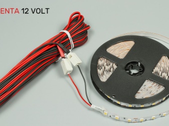
The choice of wires for LED strip
It is not enough to buy or assemble a light-emitting diode (LED) lamp - you also need wires to supply power to the diode assembly. From how thick the wire cross-section will be, it depends how far from the nearest outlet or junction box it can be “forwarded”.
Wire Sizing Criteria
Before deciding what size the wires will have, they figure out what total power the finished lamp or LED strip will have, what power the power supply or driver will "pull". Finally, the cable brand is selected based on the assortment available on the local electrical market.
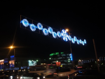
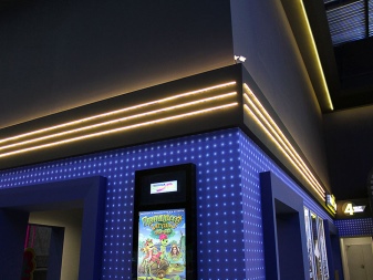
The driver is sometimes located at a considerable distance from the light elements. The billboards are illuminated at a distance of 10 m or more from the ballast. The second area of application of such a solution is the interior design of large sales areas, where the light tape is located on the ceiling or directly below it, and not next to the employees of the store or hypermarket. Sometimes the voltage going to the input of the light tape is significantly different from the value given by the power supply device. Due to the reduced wire size and the increased cable length, current and voltage are lost in the wires. From this point of view, the cable is considered as an equivalent resistor, sometimes reaching a value from one to more than ten ohms.
So that the current is not lost in the wires, the cable cross-section is increased in accordance with the parameters of the tape.
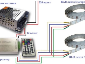
A voltage of 12 volts is more preferable than 5 - the higher it is, the less the loss. This approach is used in drivers that output several tens of volts instead of 5 or 12, and the LEDs are connected in series. 24-volt tapes can partially solve the problem of losing excess power in the wires, while saving on the copper itself in the cable.
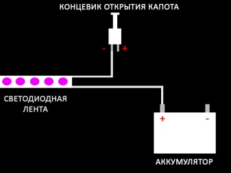
So, for an LED panel composed of several long strips and consuming 6 amperes, there is 0.5 mm2 of cross-section per 1 m of cable in each of the wires. To avoid losses, the "minus" is connected to the structure body (if it stretches far - from the power supply to the tape), and the "plus" is run through a separate wire. Such a calculation is used in cars - here the entire on-board network provides power via single-wire lines, the second wire for which is the body itself (and the driver's cabin). For 10 A it is 0.75 mm2, for 14 - 1. This dependence is non-linear: for 15 A, 1.5 mm2 is used, for 19 - 2, and finally, for 21 - 2.5.
If we are talking about powering light strips with an operating voltage of 220 volts, then the strip is selected for a specific automatic fuse according to the current load, noticeably less than the operating current of the machine. However, when the task is to make the shutdown forced (very fast), then the load from the tape will exceed a certain limit indicated on the machine.
Low voltage tapes are not threatened with overcurrent. Choosing a cable, the consumer expects that the possible drop in the supply voltage if the cable is too long will be covered almost completely.
The line should be as short as possible - low voltage requires a larger cable section.
By belt load
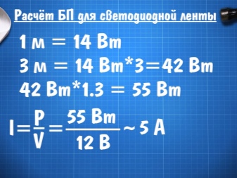
The power of the tape is equal to the current strength multiplied by the supply voltage. Ideally, a 60-watt light strip at 12 volts draws 5 amps. This means that it should not be connected through a cable whose wires have a smaller cross-section. For trouble-free operation, the largest margin of safety is chosen - and an additional 15% of the section is left. But since it is difficult to find wires with 0.6 mm2 cross-section, they immediately increase to 0.75 mm2. In this case, a significant voltage drop is practically excluded.
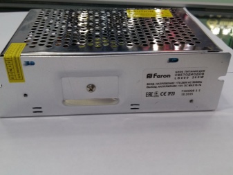
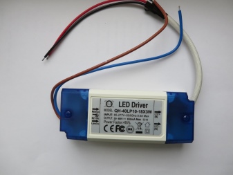
By block power
The real power output of a power supply or driver is the value originally declared by the manufacturer. It depends on the circuit and parameters of each of the components that make up this device. The cable connected to the light strip should not be less than the total power of the LEDs and the total power of the driver in terms of the conducted power. Otherwise, the current on the light strip will not be all. Significant heating of the cable is possible - the Joule-Lenz rule has not been canceled: a conductor with a current exceeding its upper limit becomes at least warm. The increased temperature, in turn, accelerates the wear of the insulation - it becomes brittle and cracks over time. An overloaded driver also heats up significantly - and this, in turn, accelerates its own wear.
Regulated drivers and regulated power supplies are tuned so that LEDs (ideally) don't get warmer than a human finger.
By cable brand
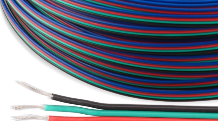
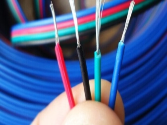
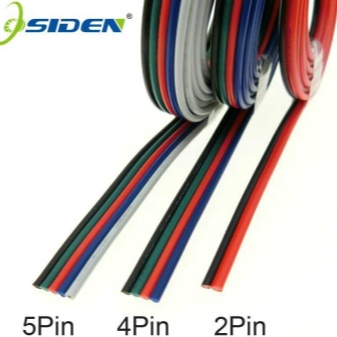
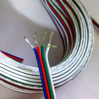
Cable brand - information about its characteristics, hidden under a special code. Before choosing the optimal cable, the consumer will familiarize himself with the characteristics of each of the samples in the range. Cables with stranded wires are considered the best option - they are not afraid of unnecessary bending-unbending within reason (without sharp bends). If, nevertheless, a sharp bend cannot be avoided, try not to allow it again in the same place. The thickness (cross-section) of the power cord with which the adapter is connected to the 220 V lighting network may not exceed 1 mm2 per wire. For tricolor LEDs, a four-wire (four-wire) cable is used.
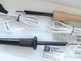
What is required for soldering?
In addition to a soldering iron, solder is needed for soldering (you can use the standard - 40th, in which 40% lead, the rest - tin). You will also need rosin and soldering flux. Citric acid can be used instead of flux. In the era of the USSR, zinc chloride was widespread - a special soldering salt, thanks to which the tinning of conductors was carried out in a second or two: the solder almost instantly spread over freshly cleaned copper.
In order not to overheat the contacts, use a soldering iron with a power of 20 or 40 watts. A 100-watt soldering iron instantly overheats PCB tracks and LEDs - thick wires and wires are soldered with it, not thin tracks and wires.

How to solder?
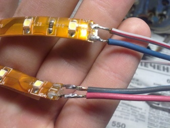
The joint to be treated - of two parts, or a part and a wire, or two wires - must be pre-coated with flux. Without flux, it is difficult to apply solder even to fresh copper, which is fraught with overheating of the LED, board track or wire.
The general principle of any soldering is that a soldering iron heated to the desired temperature (often 250-300 degrees) is lowered into the solder, where its tip picks up one or several drops of alloy. Then he is immersed to a shallow depth in rosin. The temperature should be such that the rosin boils at the tip of the sting - and not immediately burns out, splashing out. A normally heated soldering iron quickly melts the solder - it turns the rosin into steam, not smoke.
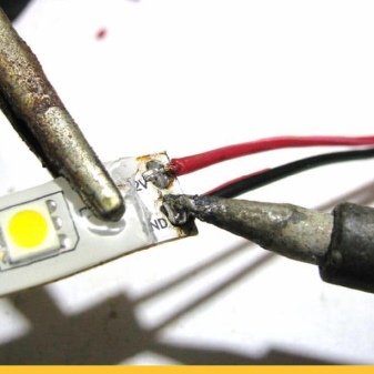
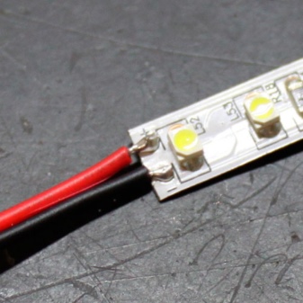
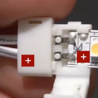
Observe the polarity of the power supply when soldering. The tape connected "backwards" (the user confused "plus" and "minus" when soldering) the tape will not light up - the LED, like any diode, is locked and does not pass the current at which it would glow. Counter-parallel connected light strips are used in the external design (exterior) of buildings, structures and structures, where they can be supplied with alternating current. The polarity of the connection of light strips when powered by alternating current is unimportant. Since people are much less outdoors than indoors, flickering light is not as critical to the human eye.Inside, at an object where a person painstakingly works for a long time, for several hours or all day, lighting flickering with a frequency of 50 hertz can tire the eyes in an hour or two. This means that inside the premises the light strips are supplied with direct current, which forces the user to observe the polarity of the luminaire components when soldering.
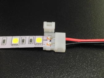
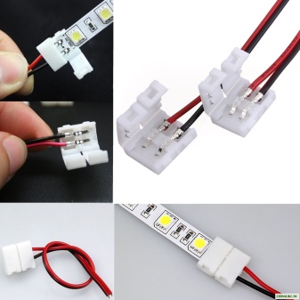
For the finished light tape, the supplied standard terminals and terminal blocks are often used, which makes it easy to replace the wires, the tape itself or the power driver without disassembling the entire subsystem. Terminals and terminal blocks can be connected to wires by soldering, crimping (using a special crimping tool) or screw connections. As a result, the system will take on a finished form. But even for exclusively soldered wiring, the quality of the light tape will not suffer at all. In all cases of assembling and installing lighting products, some skill is required to assemble, attach and connect them quickly and efficiently.


The comment was sent successfully.