Controlling the addressable LED strip via Arduino
The addressable LED strip and Arduino will help to decorate the interior of the house, create a special atmosphere, and make a ticker on the shop window. From the article you will learn about connecting and managing the tape, about how the check and flashing of the tape is done, what effects are achieved.

Advantages and disadvantages
In the Arduino addressable LED strip, the brightness and operating mode of each diode are set separately.
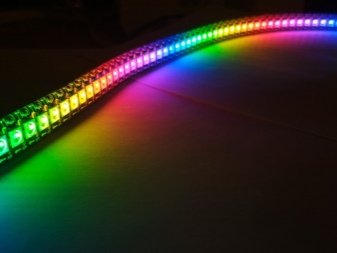
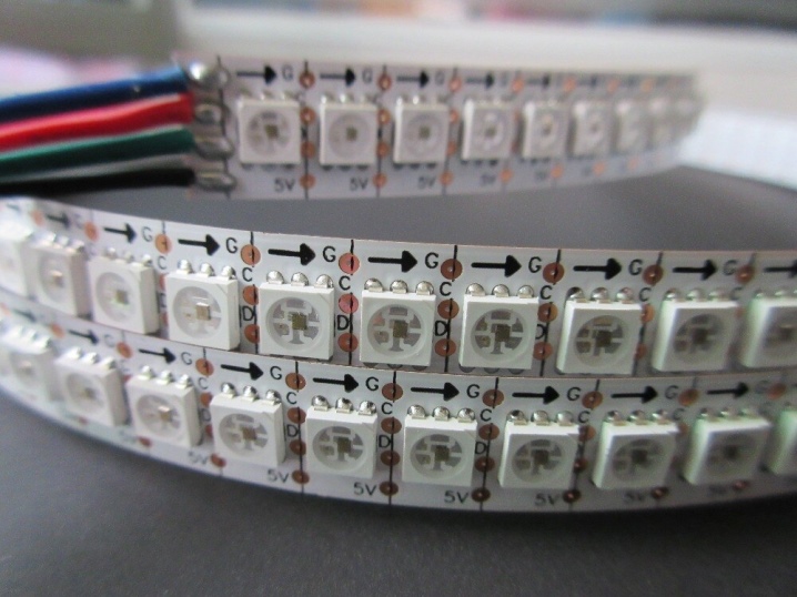
In RGB tapes, red, green and blue LEDs are combined into a block, which is more correctly called a pixel. Pixels are controlled independently of each other.
Such devices have many advantages.
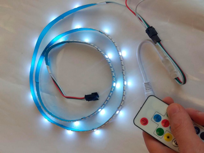
- They can be used for smart lighting. It will not be difficult to assemble a dynamic backlight, a creeping line, or make the light turn on on schedule. Connect additional modules, for example, a motion sensor, and when you enter the room, the light will begin. And also their work can be controlled remotely from the remote control and smartphone.
- Easy to customize. You can write programs for work yourself or use ready-made templates.
- LED strips are reliable and durable. They do not heat up and do not require high energy costs.
- Accessibility is another plus. Diode tapes are widespread on the market, it will not be difficult to choose the right one. The most budgetary ones cost 200 rubles. per meter, brighter - from 500 rubles.

But there are also disadvantages.
- A separate power supply of 5 or 12 V is needed. The Arduino unit can only provide 800 mA of current, which is only enough for 13 pixels (one pixel consumes 40-60 mA).
- The joints are demanding on the quality of the solder.
If you know how to solder well, then it will not be difficult to assemble the circuit. And if you don't know how, then it's time to learn. So feel free to start choosing lighting equipment.
Ribbon selection
Please note a few points before purchasing.
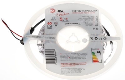
- The number of pixels per meter. There can be 30, 60, 74, 96, 100 and 144. The more there are, the richer the picture is, but the more expensive the tape. And the more it consumes energy (more powerful and more expensive power adapter).
- The degree of security. For indoor lighting, IP30 is sufficient (dust protection). For wet conditions, the diodes must be covered with silicone and the degree of protection is IP65. And if the strip is on the street, then the protection should be the greatest - IP67 (the device is completely hidden in a silicone box).
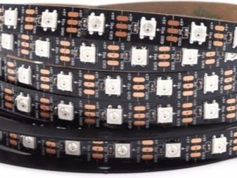
- The underlay affects the aesthetic experience. It comes in black (Black PCB) and white (White PCB).
- There are "economical" options for LED strips. They are marked with the letters ECO. These models are not as bright as the usual ones and are of inferior quality. But they are cheaper.
Now that you have found the ideal one, proceed to the assembly.
Connection and configuration
A power adapter is required to connect. Calculate its power. To do this, multiply the current consumption of one pixel (usually 60 mA) by the number of pixels in a meter of tape and by its length. Multiply the result by the operating voltage (these data are indicated in the marking). Don't forget the safety factor.
For example, a tape has 60 pixels per meter. Required length - 1.5 m. Supply voltage - 5 V. Safety factor - 1.3.
Then the power of the adapter should be:
(60 mA / 1000) (current in A) * 60 pixels / meter * 1.5 meters * 5 V (voltage) * 1.3 (headroom) = 35.1 W. Round up to the nearest higher - 40 watts. Such a power supply is needed if the tape glows with white light. If not, the power of the adapter can be reduced by 1.5-2 times.
Important! For different models, you need either 5 V or 24 V. Read the label carefully.
In addition to the power supply, you will need an Arduino Uno board and connecting wires with a cross section of at least 1.5 mm².And also resistors with a resistance of 10 kOhm and capacitors with a capacity of 470 μF (more is possible).
When everything is ready, get to work.
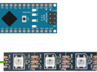
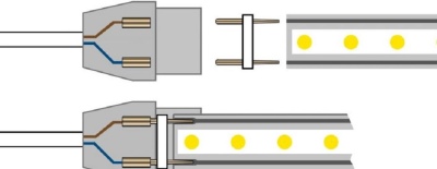
- Find the beginning and end of the tape. The commands sequentially move from one pixel to another, and the direction of their movement is indicated by arrows. If there are no arrows, then the control contact at the beginning is denoted by the letters DI (digital input), and at the end - DO (digital output). The DO contact is used to connect additional tapes.
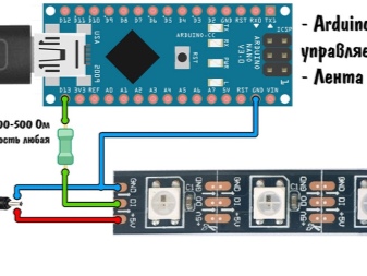
- Solder a 200-500 ohm safety resistor. If the power supply suddenly fails, the current will not flow through the USB connector and will not burn it.
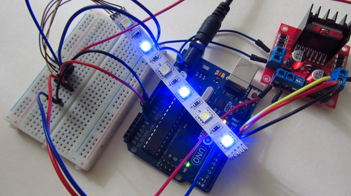
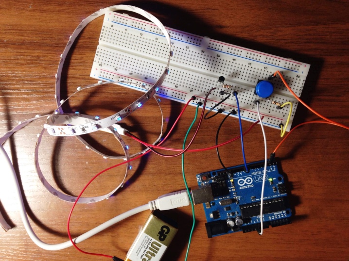
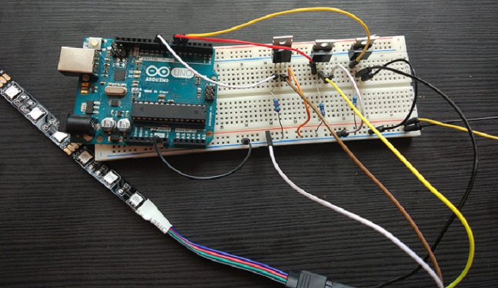
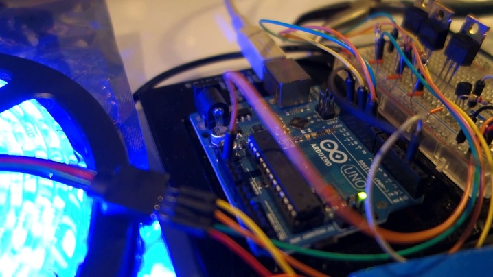
- Assemble the diagram. If the device is controlled from a computer, the circuit should be like this.
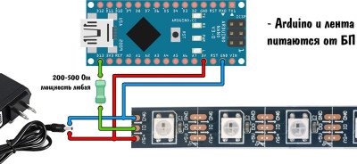
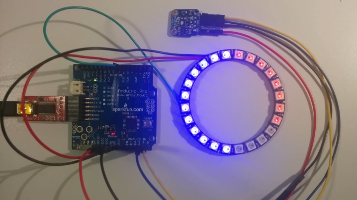
For autonomous operation or control from sensors, you need one.
Important! Do not allow static electricity during installation.
Wear rubber gloves, and periodically lean the soldering iron to ground (at least to the steam heating pipes).
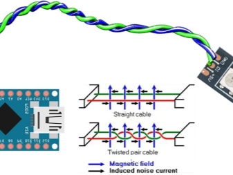
- If the distance between the diode strip and the Arduino board is more than 15 cm, then twist the control DI and ground GND wires into a pigtail. Then there will be no pickups.
- In flashing mode, there is interference on the power line. This leads to unstable performance. To smooth out the noise, a capacitor with a capacity of 470 μF and a voltage of 6.3 V.
- To make it smoothly turn on, the circuit is assembled on a breadboard for assembling circuits on microcontrollers. It must have 3 logic levels of N-channel MOSFETs.
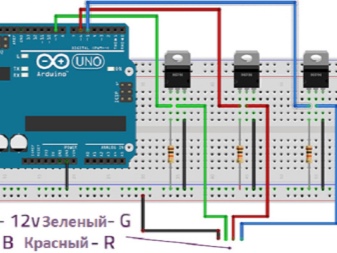
This is how it looks in reality.
- If the tape is long, then voltage losses will appear in it. Therefore, the outermost pixels will shine dimly. To avoid this, supply power to the joints of 2 diode strips or through each meter of total length.
It only remains to check the circuit. To do this, write the simplest program.
- Connect the board to your computer and open the Arduino IDE.
- Download a library or template. The most famous libraries are FastLED and Adafruit NeoPixel.
- FastLED is very versatile and supports all Arduino versions. Hence the disadvantage - it takes up a lot of memory, and most of the features will not be useful.
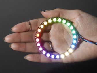
- The Adafruit NeoPixel is designed for NeoPixel Rings, but will work with any LED strip. It has fewer effects and slower speed, but the Arduino memory is freer. This means that more operating modes can be loaded onto the board.
Now you can implement all your projects.
Important! Load the program into the Arduino memory only when the tape will definitely not work. To do this, either disconnect it from the board, or connect the power supply in advance.
If you do not do this, then when you flash the device, the entire supply current will go to the board. The board or USB port will burn out.
But it so happens that the address tape does not work correctly. Check out the most common mistakes.
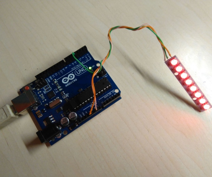
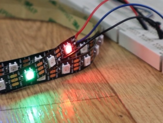
- If the diodes are lit with a red tint, then the power supply is too weak. Or the connections are broken and they need to be re-soldered. Another option is power wires that are too thin.
- When the device is buggy or works with artifacts, then the matter is in the power supply. Try replacing the wires with shielded ones or turning off Wi-Fi.
- If the pixels do not glow at all, then most likely the circuit is assembled incorrectly. The most common mistakes: the ground of the tape is not connected to the ground of the Arduino board, the DI control wire goes to the end of the tape, and not to the beginning, the power wires (5V and GND) are reversed. In all these cases, it is enough to rebuild the circuit.
- But if you connected the assembled device without a resistor, then, most likely, it immediately burned out. Then you need to change the control board.
As you can see, learning Arduino is easy. And if you suddenly have problems, then ask questions on the forums. They will be happy to help you (especially if you go under the girl's nickname).


The comment was sent successfully.