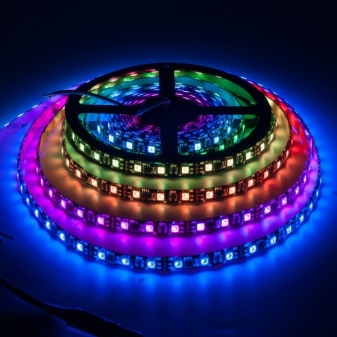
Addressable LED strips
Unlike simple monochrome or white LED strips, which do not need anything other than supplying the appropriate voltage, addressable LED strips are more difficult to configure. They provide a dynamic light source that adds an extra touch of appeal to any room.
What it is?
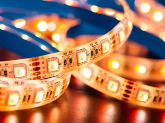
Addressable LED strips (diode, pixel, LED strips, as they are otherwise called) are not a simple set of LEDs lined up or assembled in a different topology. Each diode is controlled separately and independently of the others. The prototype of the tape is an LED matrix, each pixel of which is a triad of red, green and blue LEDs.
A controller in a matrix or tape allows each of the LEDs to glow with different brightness.
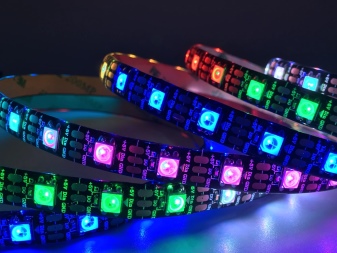
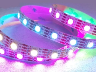
Just as an LED matrix monitor or a smartphone display gives a specific image, an address strip allows you to organize the effect of "running lights" with any color, enable or disable individual LEDs at any site and at any point.
Principle of operation
Red-blue-green LED strips have gained popularity, allowing up to 16,777,216 shades that the human eye can perceive. Each of the LEDs has its own miniature microcircuit-controller that allows you to set it exactly the color of the glow that the user requested. The presence of a separate microcontroller near each LED, however, leads to a significant increase in the cost of such a tape.
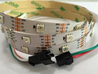
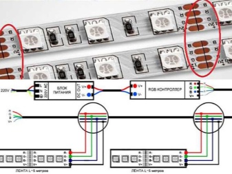
Common contacts for connecting the tape - no more than 4, but not less than 3. One common contact - "mass" - serves as a ground for the driver housing. The second one supplies a positive supply voltage of 5 volts. The third (and fourth) - sends program signals from the general microcontroller board.
The address tape is digitally controlled. Working without a shared controller will not produce any results. At best, you would end up with continuously glowing LED triads emitting a cool whitish (bluish) light. If the user touches the digital bus sending signals with his finger, the controller will take this interference as a command and light up all the LEDs or several of them. The supply voltage for each segment is 5 or 12 volts.
The transmission of the control signal is carried out sequentially between all segments, and not at once. Due to this feature, if one microcircuit is out of order, then the command will not go further, and subsequent LEDs in the same circuit will not light up.
It is possible to complicate the control algorithm of such tapes by "hanging" additional microcontrollers into the control circuit.
Overview of ribbons
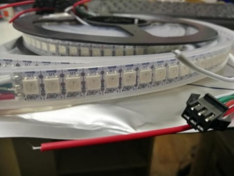
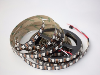
The tapes that gained the most popularity among the people were assemblies based on the WS2812b and WS2811 microcircuits. They are designed for 5 and 12 volts, respectively.
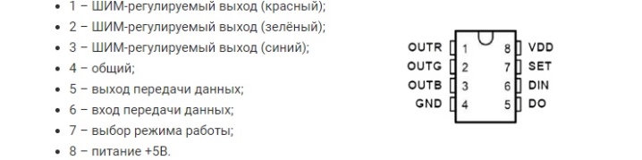
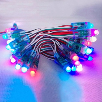
- Pixel tape based on WS2811 chip characterized by the presence of at least 8 outputs for each of the auxiliary controllers. Three of them are responsible for the red, green and blue colors, two - provide data exchange, one - to enable the desired operating mode, one - for power supply and the last - for "ground". A more "advanced" version of the WS2811 assembly has a significant difference from its predecessor: the point (local) controller turns on with three LEDs at once, which significantly increases the cheapness and reliability of this model.
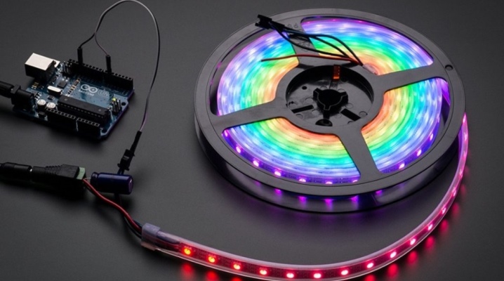
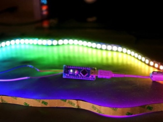
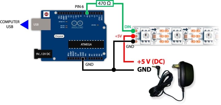
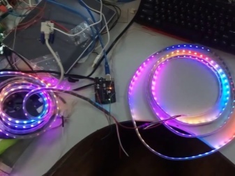
- WS2812B based tape management carried out by means of a separate controller serving as a program unit. Radio amateurs assemble such devices based on Arduino boards using a small program script written in the C ++ programming language. To increase the noise immunity, electrolytic capacitors are connected in parallel to the LEDs - in strips based on any microcircuits. An additional feature of this model is that the point control crystal is placed in the SMD-5050 assembly, and the 4 outputs are labeled as "power", "ground", "send" and "receive". It is powered by 12 V.
- Difference of the WS2813 version from the previous one in this list - additional redundant output, which allows you to transfer commands from the common controller further. This avoided premature failure of any of the point controllers in the chain - in terms of the operability of the subsequent tape sectors located behind it.
Summarizing the patterns of functioning, it is worth noting the following. As part of smart tapes, a PWP controller is used, located directly in the SMD LED case. The 5050 series has just such a control scheme. A single unit - light-emitting diodes and the simplest controller - allow you to collect a tape of any length on such an LED. The number of pins of such an assembly is from 4 to 8 for each light element.
The only thing is that to create a 10-meter (or more) tape you will need reinforced (with an increased cross-section) current-carrying terminals "power" and "ground" - the low voltage drops noticeably with a small wire cross-section, which cannot be said about the high one.
Scope of application
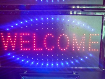
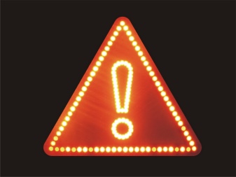
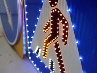
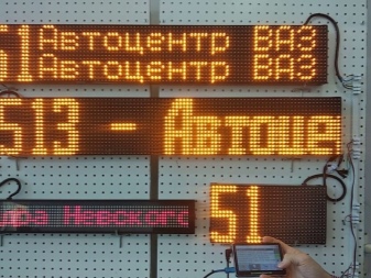
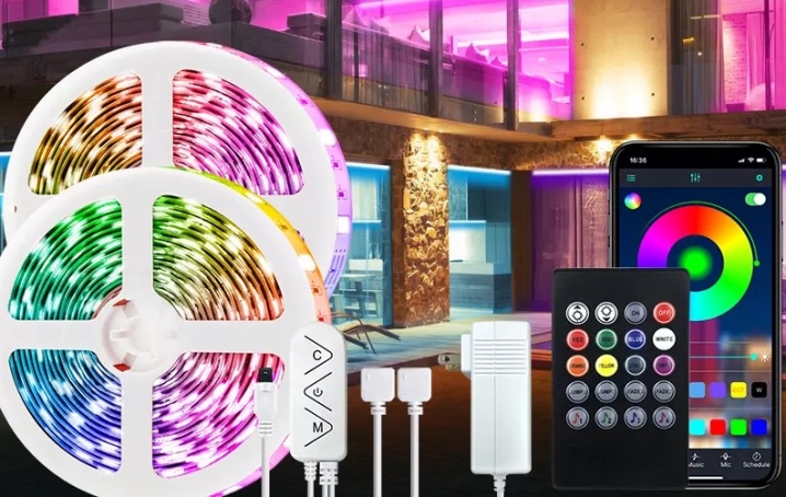
Modular LED strips with software defined glow went even further in their development. If a single-row assembly is used as a ceiling lighting, then by arranging their rows one above the other and placing them on a rectangular base, you can create a board of any format. Electronic road signs and signs are an example: as soon as the day turns into twilight, they turn on automatically and operate on a battery charged during the day from a solar battery. Single-row assemblies often come with a remote control.
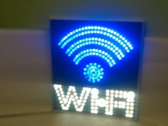
For example, on one of the bridges of the entrance route to a large city, every 5 seconds, the inscriptions replace each other - "Drivers, happy journey!", "City N welcomes you!" This is just one of tens of thousands of cases of such use of LED arrays made of strips. And when assembling a full-fledged screen for a billboard, the organizer becomes available to broadcast advertising for discounts from nearby hypermarkets. Such assemblies are equipped with a Wi-Fi module for receiving streaming video from any gadget or PC that also has a Wi-Fi module.
The diagonal of the screen for displaying advertisements and programs reaches several meters.
Single-color ribbons (for example, glowing red), typed in matrices, are used as store signs. A running ad line can display up to a kilobyte of text (excluding spaces). It uses mainly a one- or two-line scoreboard. The information is displayed sequentially - for example, the inscriptions change each other: "Look at restaurant X", "The best dishes" of "Ukrainian cuisine", "Cozy place", then the display cycle of these inscriptions restarts - and so on until the display is turned off by night.
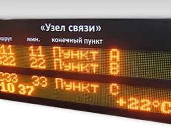
An example of a bus display is a short list of the main streets of its route and the number of the latter. Similar systems are installed at railway, air and bus stations - points A and B (cities of departure and arrival), the time of departure and arrival of a particular type of transport are displayed near each seat. Placards are placed in the waiting room and in parking areas.
How to connect?
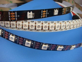
Connection is carried out in accordance with specific instructions. If not, inspect carefully the identification marks on the printed circuit board pins and on the assembly case. So, the signs "+ 5V", "Mass", Rx and Tx should not be in doubt - this is the simplest 4-wire protocol, according to which elements of the same structure are connected to each other. Do not apply 12 V if there is a 5 V marker on the board (not 12 V) - the tape will simply burn out.
Some LED strips may contain a resistor connected in series at the output of the microcircuit with a resistance of several to several tens of ohms.
These resistors extinguish excess voltage on LEDs included, for example, in the on-board network of a car or truck, bus, and so on.
The fact is that to charge the battery, the car network (generator on a gas engine) uses a charging voltage of up to 15 volts, and a fully charged battery produces up to 13.8 volts. For a 12-volt build, that's a lot - so that LEDs and controllers do not burn out from overheating, and ballast resistors are installed. Constant "overheating" of the LEDs (up to +70 or more) will allow them to work not declared 25000-50,000 hours, which is equivalent to about 10 or more years of continuous operation, but only 1500-4000.
In other words, electronics overloaded in current and voltage would burn out in a few months. In some cases, when you notice that, despite the nominal voltage, the LEDs and controllers still overheat - reduce the voltage to 9-11 V so that the light from the tape remains visible from afar.
The Tx and Rx pins cannot be reversed. The Rx input of the tape is connected to the Tx pin of the general controller.
It is foolish on the local controller to wait for receiving commands from the general - when the second does not send anything, and also "listens" to the line, waiting for response commands from the first.
The fact is that the control (master) programmer ("brain" of the system), before sending control commands to any of the local microcontrollers (performers), must send a test message and receive a response signal from them informing them of their readiness for work. If this did not happen (the dotted microcircuit "died"), then the interrogation message from the "brain" will go further until the first LED chip following the burned-out one responds. The correctness of the assembly must be checked immediately.


The comment was sent successfully.