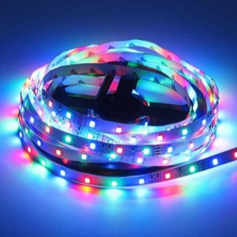
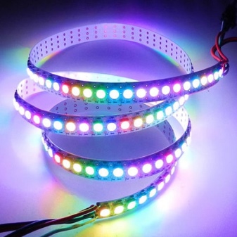
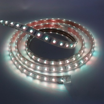
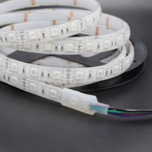
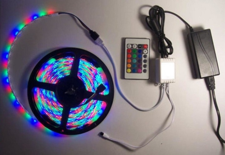
RGB and RGBW LED Strips
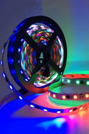
LED strips with conventional white LEDs as well as dynamic light (red, yellow, blue and green) are ubiquitous. Their hybrid - four-color or RGBW-stripes give out, in addition to the basic three colors, in addition, and white.
What it is?
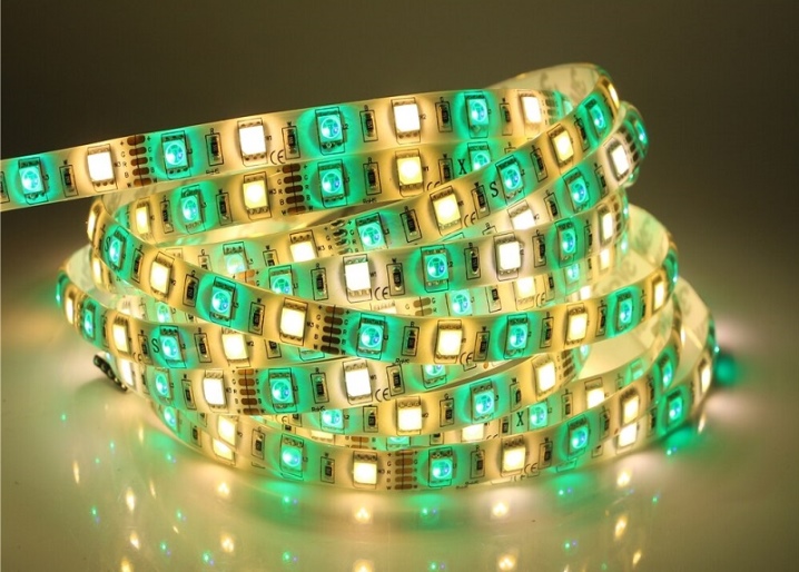
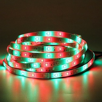
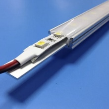
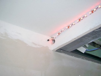
The RGB LED assembly is an addition to the light strip, which shines with an exceptionally white light. In the simplest case, when RGBW strips were not at hand, colored stripes are laid next to white light strips - either one by one (for each color), or all at once, alternating with each other white, red, green and blue glow colors.
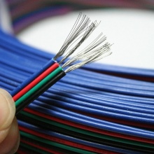
Progress does not stand still - composite LEDs appeared on the market, producing white, red, green and blue colors. There are 4 simple light crystals built into such a composite LED, each of which gives its own color. For control, either a 5-pin (5-wire) line is provided, or a two-wire line, through which power is supplied to the LED, which has a primitive microcontroller. In the latter case, 5 crystals are placed in the "multi-LED": 4 light-emitting, one (the simplest chip) control. As a chip, a multivibrator (dimmer) is provided, which sequentially supplies power from itself, which comes via an external two-wire line, to the corresponding light crystals.
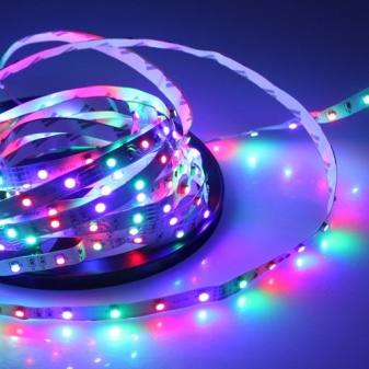
An analogue of RGBW is a five-component (5-critical) LED, which also contains a yellow one. An RGBW assembly would become an RGBWY LED. Such a modification of multi-element LEDs has not found application in practice - the yellow color is reproduced by the simultaneous glow of red and green light crystals. Light crystals located close to each other, when the observer is one or two meters away (and further) from them, merge in his field of view into a single light point. This feature of vision, discovered by Lomonosov and confirmed in practice by Helmholtz, allows you to create an arbitrary shade from the 16,777,216 variations visible to the eye. By changing, for example, the brightness of the red and green glow, a person sees a reddish-yellowish tint of light on the RG-LED.
RGBW strips have an interesting feature - light compensation. If the white light crystal suddenly fails, then using the red, blue and green that are still working, you can recreate a dynamic whitish light - from cold to warm, setting the appropriate brightness. The ratio of the luminance signal of these three LEDs for plain white (without shading on the color temperature scale) is as follows: 30% of the light gives red, 59% - green, 11% - blue.
If you reduce the green glow a little and add blue, the shade will be cold white. If you subtract blue and add red, the hue becomes warm white. Etc. In industrial light strips, this process is not controlled by a person, but by a special device - a dimmer microcontroller, which sets the shades and frequency, an algorithm for changing them over time.
A built-in microcontroller with rigidly set lighting modes is located in each of the LEDs: when such a light strip is turned on, all four light elements light up simultaneously. Smooth or abrupt cyclic switching is set using an external dimmer. Address (algorithmic) - using an additional digital (three-wire communication line).
In the latter case, such systems are significantly more expensive than simple RGBW tape.
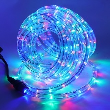
Summarize. LEDs W - white are the main ones. These are light elements that provide light for the daily life of people at home and at work. Crystals R, G and B - red, green and blue give background illumination. So, in LED chandeliers, controlled from the remote control, the owner chooses the illumination on his own. For example, on New Year's Eve, users often turn on an RGBW tape or lamp in the "running lights" mode, like on a Christmas tree garland: red, green and blue flash sequentially or at different intervals.
The ceiling illuminated in this way gets an elegant, festive look. Users who prefer sharp blinking, blinking to a smooth transition from one color to another, choose another mode. The use of arbitrarily programmable Arduino microcontrollers allowed each owner of such a light tape to set their own algorithm, not limited to one or more factory presets.
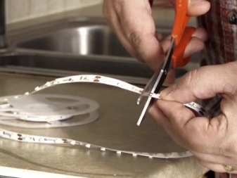
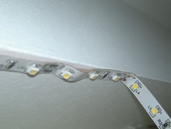
Flexible RGBW tapes - at 5, 12 and 24 volts, unlike 220-volt ones, are cut into sectors shorter than 0.5 or 1 meter. Ceilings, walls and floors with stepped transitions are lined around the perimeter using short and long segments connected by 90-degree connectors that create turns of the tape at this angle. This means that a dynamically illuminated room takes on an elegant and complete look. The simplest light strips without dimmer switching are connected directly. They will need a power supply (adapter, driver) with two independent output voltages: 2 volts for colored LEDs, 3 for white ones.
Necessary accessories and components
In addition to the multi-color diode tape, the master will need such accessories and components.
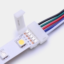
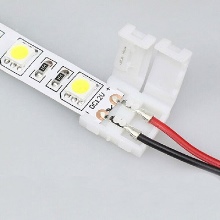
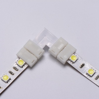
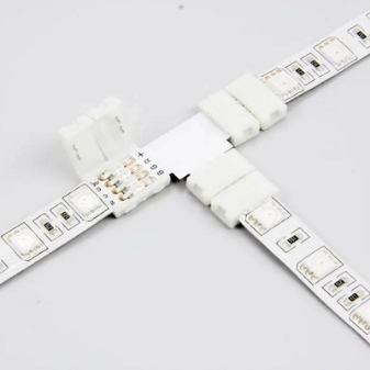
- Corner connectors.Most often these are rectangular connectors - one turn. Tees can be used - T-shaped adapters-connectors. The "crosses" are used to connect intersecting multi-wire buses, their "pluses" and minuses are electrically isolated from each other. Asterisks - in special cases: 5, 6, 7 and more terminal ones allow one of the tapes to provide a connection to the power supply unit, and the center of the "star" - the multiconnector into several strips will share the supply voltages with the rest of the tapes. Connectors - "crosses" and "stars" are poorly distributed, due to their uniqueness - a user who knows how to solder collects such a topology using pieces of wire.
- Power cable - when there are many tapes, a decent cross-section is required. A 12 volt tape with a capacity of, for example, 10 watts per meter, consumes almost an ampere. Therefore, 5 m of light tape will consume: 5/6 A, multiplied by 5 m, will give 25/6, or more than 4 A. And given the heat loss (to LEDs and wires under load), only 2.5 A will reach the tapes. The light assembly did not disappoint you with a low luminosity than stated by the manufacturer, you need a cable with a margin that allows you to supply 10 A without a noticeable drop in the supply voltage under load. Many home-builders, faced with this need, take a common piece of cable to which several light strips are connected, with a cross section of 2-5 mm2 - and they do not miscalculate: if the power supply is powerful enough, the light strips glow with the declared brightness.
- Universal adhesive. You can use "liquid nails", reminiscent of the "Moment-1" glue.

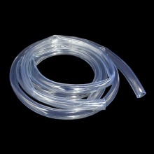
- White box with a transparent lid (possibly with a diffuser) or a transparent silicone tube. In the latter case, a garden or technical hose that transmits white light is suitable - with an inner diameter of about a centimeter and a small one. Packing the tape will make the assembly waterproof and dustproof. Ready-made light strips with a moisture protection class IP-69 are already placed in a dust and moisture resistant shell. The sealed light tape, although it loses a little - up to 10% of the luminosity in the shell, is extremely protected from external weather and microclimatic (mechanical and chemical) influences.
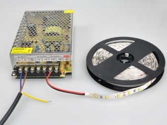
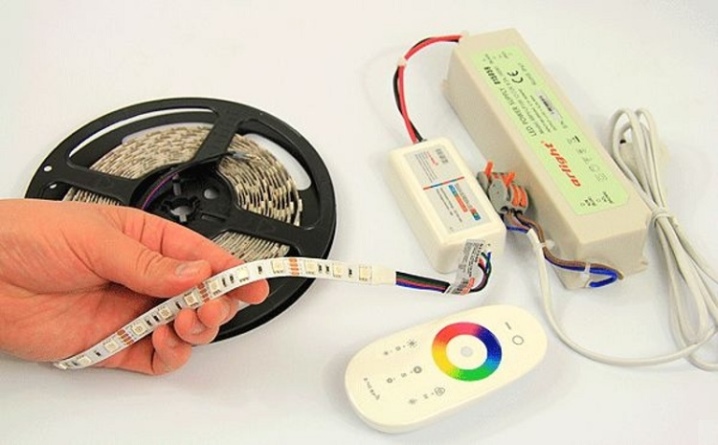
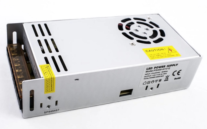
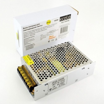
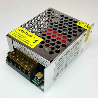
- Power Supply. Can be supplied as a set. If an RGBW tape without a controller, it works from 220 V, i.e."From the socket", then a mains rectifier is mounted on the power cord as a device in a mini-capsule. This is a high voltage diode-rectifier bridge. Parallel to it - a high-voltage capacitor is connected at the output, as a rule, with a margin of voltage drops up to 400 V.
- Various fasteners: dowels and screws for them. Required to hang the power supply.


Tools - a knife for stripping wires and contacts, a soldering iron with solder, rosin and soldering flux, a screwdriver. Soldering is needed in non-standard cases, when there are no connectors with the required topology, but you need to hang the light elements.
Some terminal blocks have screw terminals.


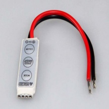
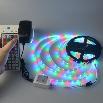
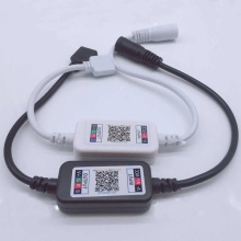
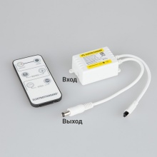
Controller
Controller functional unit - a mini-board in a case with outputs is connected to the power supply via the corresponding input on it. As a rule, these are the terminals "+ 5V" (or 12 V) and "ground" ("mass"). The controller outputs are also load outputs: the microcircuit controls the power supply through power transistor stages, which work as switches. As a rule, these are "minuses" on "R", "G", "B" and "W", and they have a common "plus", but there is also a reverse polarity - with a common "mass". A 5-wire power line is formed.
The complicated scheme is as follows: "plus" and "minus" are the only ones here. The common power supply is suitable for the LED (groups of light crystals). The chip in the LED case independently - locally switches the glow colors. Then the "minus" "sits" on the common wire, the "plus" goes separately, and in the control bus there is a high-speed line according to the digital protocol - wires for "reception" and "transmission".
The controller, detecting that the light chips are connected and ready for operation, sends them address commands via the bus ("Rx" / "Tx" / "ground"). Suddenly connecting "plus" to "reception" or "transmission" is a common mistake of novice craftsmen: chips and a head controller ("brain") that have no protection will instantly burn out (thermal and electrical breakdown of the microprocessor part).
The fact is that the high-frequency-pulse voltage with which they work is hundredths and thousandths of a volt - a few or more volts will instantly "kill" the electronics.

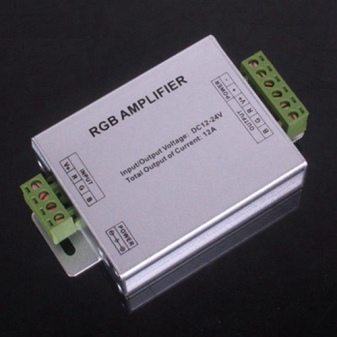
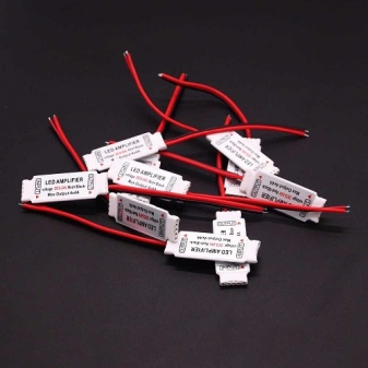
Amplifier
An amplifier of digital signals from a complex ("intelligent") control system for RGBW-light tape is required when the length of the program line is hundreds or more meters. To compensate for the losses of the high-frequency voltage, which is already scanty, and its amperage is a few microamperes, the so-called. booster. Finding and choosing it is problematic - only a few companies produce this product, since such situations are very rare. Enthusiasts assemble such circuits on their own by purchasing radioelements in China online.
As for the power amplifier - when the light strip in the last sections "sags" in brightness, it is sometimes cheaper to purchase an additional adapter for 5, 12 or 24 volts than to invest several times more money on multicore cables with a thick cross-section. The disadvantage of this solution is that the power supply unit, for the sake of the integrity of the original design of the room, is hidden under the suspended structure of the chandelier, behind it - from the side opposite to the entrance to the room. Power is supplied via additional wires through redesigned connectors to which small wire leads are connected.
Power Supply
As an adapter, any module that steps down from 220 to 12/24 volts is suitable, providing isolation from the high voltage of the network. It turns alternating voltage into constant voltage - thanks to it, the light strips do not flicker, tiring the user's eyes during many hours of work, but give an even, pulsation-free main light and background illumination.
Selection Tips
Avoid using light tape that flickers during operation. Ripples - with a frequency of 50-100 hertz, are also given by the simplest power supplies (a transformer and two diodes, even without a smoothing capacitor). Select and agree on the power of the power supply unit and the total consumption (in watts) of the light strips themselves.If the first is less than the second, the glow is incomplete, and the unit operates in overload mode or periodically shuts down due to overheating.
If on the contrary, the entire assembly will serve for many years without any complaints, since the power supply has a power reserve.
Connection and configuration
Follow the steps below to edit and set up dynamic RGBW lighting.
- Install the power supply. Place it in a hidden place - a niche in the wall, behind a cabinet, etc.
- Place light strips in the right places in the room.
- Connect the connectors. If the sections of light strips are connected by soldering, in advance - before placing the tape, solder the sections for hard-to-reach places for the ceiling, floor and walls.
- Install and connect the output and power cables (cords) to the power supply.
- Hang up and connect the controller (if any) following the assembly and commissioning instructions of the device.
- Lead and connect the wires (and their sections), having checked according to your individual lighting system setup plan.
Check if the system is assembled correctly. The entire light assembly should light up. If a remote control is provided, insert batteries or rechargeable batteries into it and check the switching of modes in the glow. Go through the glow modes - everything set by the factory should work. If programming from the remote control is provided, set your own algorithm for switching colors and white light. The result is a multi-colored glow, combined with or without the main (white) one.


The comment was sent successfully.