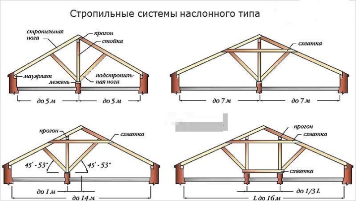
Mansard roof rafter systems
Mansard roof rafter systems are a very interesting topic for everyone who is engaged in its arrangement. It is imperative to study the nuances of a gable roof with an attic and other types of roofs, familiarize yourself with the drawings of the semi-attic roof systems. A separate important topic is the installation of rafters and their internal structure.
Peculiarities
Of course, the roof truss system differs markedly from the supporting structures on other types of roofs. The arrangement of the attic is aimed at expanding opportunities and opening up more space inside. Most often, the roof above it is associated with a 5-sided structure with a pair of slopes. All this can be based on:
-
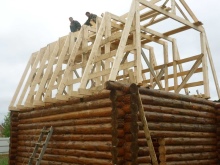
to the log house;
-
on concrete walls;
-
on brickwork.
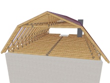
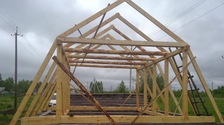
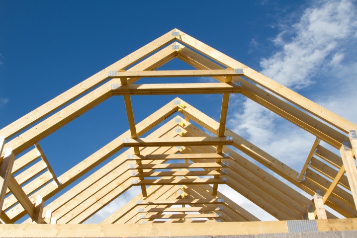
The usual device for an attic roof, including for an impromptu upper floor of a frame house, implies a different-sized slope along the slopes. The structure is cooler at the bottom than at the top. This specificity leads to the appearance of a convex kink, which is why they speak of a "broken" roof. It is worth noting that such a technical term should not be misleading.
Quite often it is found that it is impossible to visually determine these two parts and the difference between them.
Species overview
Fortified
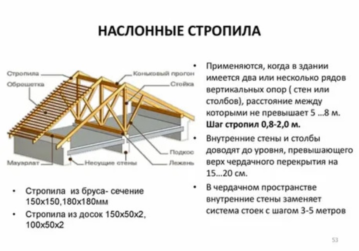
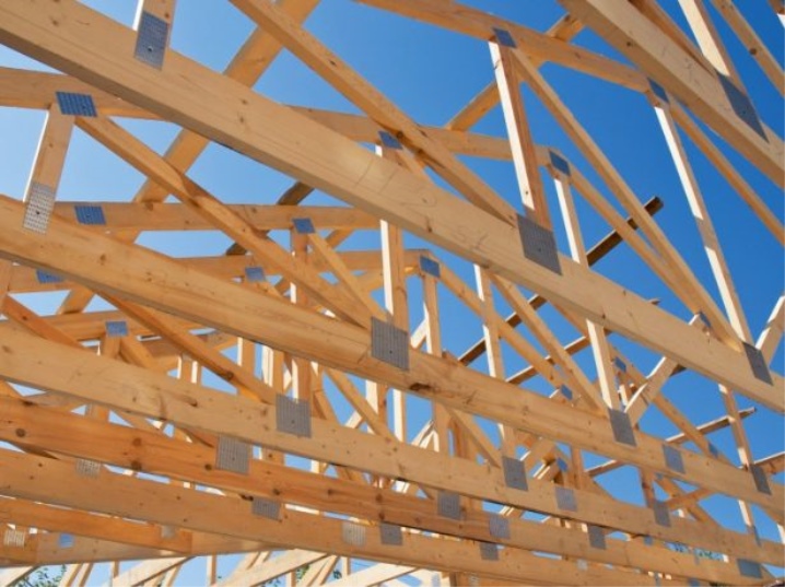
This type of rafters under a gable roof with an attic is used if there are load-bearing walls inside. They also use it if there are intermediate supports. An important advantage of this circuit is its long service life. During normal operation, ventilation through and through occurs automatically, as it were. As a result, the likelihood of rotting is minimized.
Builders appreciate the rafter type of rafters for the ease of work. You can equip such an assembly pretty quickly. Single parts of the perimeter structure are held on opposite walls. With a gable roof, a pair of inclined legs is equipped. Their tops are supported by a girder; this run itself is stabilized by the racks.
But this solution creates problems when it is necessary to increase the length of the span. In this case, the legs of the rafters can bend or even twist under increasing loads. To avoid such an unpleasant development of events allows the use of racks and struts. Such stops (subject to competent calculation) work very effectively.
They are also used for joining rafters from a row of boards in order to increase the mechanical strength.
The non-spacer subgroup is made in such a way that the rafter leg only accepts a bending load. The horizontal thrust is not transmitted to the wall. Often, a support bar is attached to the lower section of the "leg", or, due to the gash, they provide an emphasis on the Mauerlat. The top of the rafter is sawn with a bevel, the angle of which prevents lateral contact with the purlin and the formation of bending resistance. This is important because although the bending moment is almost zero along the edge, it is permissible to trim the element there very limited.
The size of the bearing zone is limited by the total section height. If you cannot cut the rafter from above (and there are various reasons for this), you will have to build it up with rafter pruning. The notch located on top should have as horizontal a surface as possible. Otherwise, the system will already belong to the spacer category, and then all calculations and approaches will have to be redone. There is no need to talk about the reliability of the previous schemes.
Most often, however, layered rafters are performed differently. They are attached with sliders. The apex is fixed using a nail fight. In some cases, a bolted connection is used. An alternative is to abut the rafters against each other and dock with toothed rafters made of metal or wood.
In some cases, they resort to rigid pinching of the ridge knot. The apex is fixed tightly. The lower part is propped up with a slide. But a rigid ridge block means a very powerful bending moment and reduces deflection. This solution guarantees a certain margin of safety and bearing capacity.
The spacer subgroup of layered rafters differs in that the supports have not 2 degrees of freedom, but only 1. The tops of the rafter legs are firmly abutted using bolts and nails. This allows a pivot bearing to be formed. The spacer complex is characterized by static resistance to various loads. Mauerlat is supposed to be rigidly installed on the wall; additionally, struts, racks, console beams are used - this solution is optimal for wooden buildings.
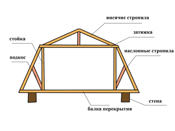
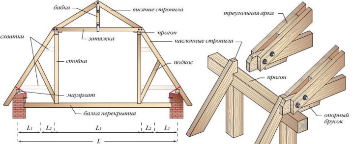
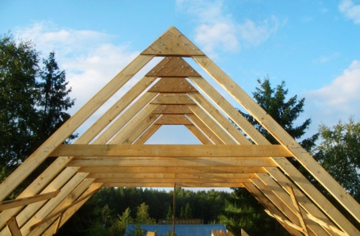
Hanging
Such rafter systems are always based strictly on the supporting walls. The legs are loaded in two directions. Substantial mechanical forces are compensated for by sophisticated tightening. These lugs tie the legs together. Puffs are made of metal or wood; they are placed at a certain height, and the higher it is, the stronger the overall connection should be.
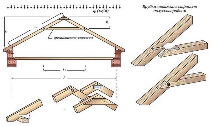
Hanging layout implies slope placement. It only transfers vertical loads. Even a slight deviation from verticality threatens the appearance of serious problems. It is very important to use a brace at the base of the roof. Such stretch marks are made from a bar; the use of both solid and prefabricated structures is allowed.
Double brace connects:
-
with an overlap;
-
with an oblique tooth;
-
with overlays;
-
with a straight tooth.
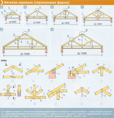
The rafter legs of the hanging assemblies are made on the basis of a log and a bar. In some cases, an edged board is used. They must be protected from fungal attack and fire. Hanging rafters are used:
-
in residential construction;
-
at warehouse facilities;
-
in industrial construction.
Combined
It is, as you might guess, about a combination of layered and hanging details. The advantage of this solution is an increase in freedom when arranging supports and internal space. This circumstance is most valuable when organizing a hall with enhanced lighting. The trusses are based on special walls or columns. The distance between the trusses is 5 to 6 m.
The rafter belts located in the upper zone become the fulcrum for the purlins. It is especially stipulated that at least 2 runs must fall on 1 slope. But the arrangement of the upper run remains at the discretion of the builders. For your information: when using rolled metal as girder parts, you can expand the permissible distance to 8-10 m.
A similar effect, although less reliable, can be observed with laminated veneer lumber structures.
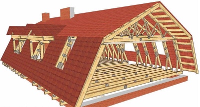
The arrangement of rafters in a sloping semi-attic roof has its own characteristics. It usually uses non-expansion layered structures. Maximum attention is paid to how it all from below joins the Mauerlat. Under a hipped roof with windows, if there is no support in the center, let's say a layered version. Even non-professionals can do it. In more complex cases, you can resort to the hipped roof modification.
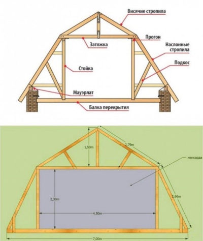
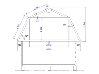
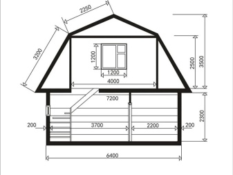
Calculations and drawings
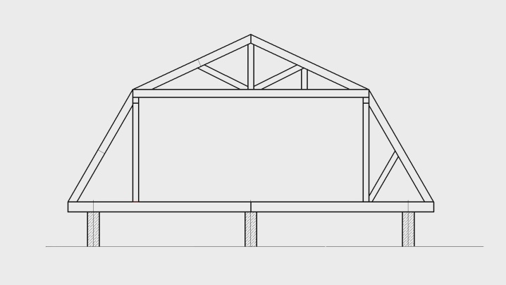
This is how the attic rafter complex with a span of more than 8 m looks roughly.The following diagram helps to present the main distances and angles in more detail. The number of support elements depends on the dimensions of the roof assembly. But in most cases it varies from 70 to 120 m. A complete calculation always includes:
-
determination of stable and changing loads;
-
establishing the optimal slope of the slope;
-
accounting for periodic loads (snow, rain);
-
input of correction factors;
-
analysis of climatic parameters of the area.
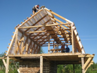
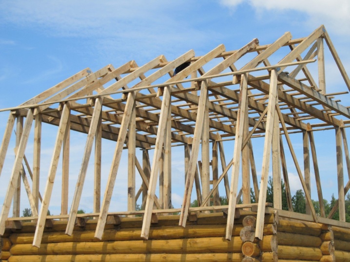
Installation of rafters
However, studying the structure of the rafters and making competent calculations is only half the battle. The most high-quality preparation can be devalued by stupid implementation, and for the roof such a circumstance is almost more important than for other construction areas. That is why it is so important to be able to do all the work step by step with your own hands.
The bars will certainly go beyond the outline of the outer wall. This requirement increases the available usable area.
The lower beam should rest on the floor; leaning on the Mauerlat is prohibited. Strut blocks according to this scheme are located under the edges of the triangular sidewalls. Do not think that their arrangement will complicate the work. After all, on the other hand, it is quite possible to abandon the Mauerlat (however, without a concrete layer, where the beams will be mounted with anchors, it will still not work). The eaves width for a wooden dwelling is at least 0.5 m, for buildings made of natural and artificial stone - at least 0.4 m; such information allows you to correctly put all the parts during assembly and immediately evaluate the finished result.
The removal of the rafters itself is made extremely clearly:
-
the first step is to fasten the outer beams, the diameter of which is at least 15x20 cm;
-
then you will have to stretch the cord connecting the extreme beams and supplement the missing beam elements in the gap (the step is different for warm and unheated rooms, it is calculated separately);
-
then they cut down the nests for the extreme supports, carefully measuring the distance;
-
prepare these supports;
-
fix temporary spacers.
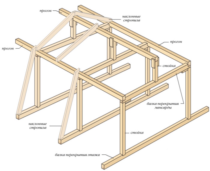
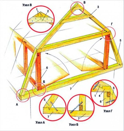
When they are ready, you need to align the points for the supports - a plumb line will help with this. If everything is correct, a pair of support blocks is placed in the middle of the fronts. They support the girders. Further, the supporting structures themselves are connected with each other and with the running nodes. In the centers of the beams, they mark where the supports and the ridge block will be fastened. Plank racks are installed at exactly the same distances.
The size of the uprights and the ceiling beams must be identical. Pre-connections are made with nails. But you will have to assemble the rafters during the final installation using corners. The initial pair of racks is fixed with lingering bars. Only then does the fastening of individual rafters begin.
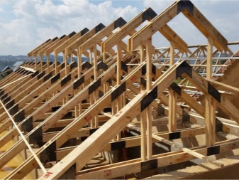
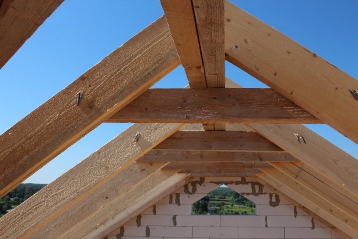
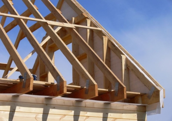
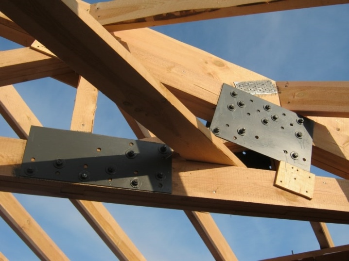
They are placed on Mauerlats or on overlapping beams. The choice of one or another option is determined by the construction plan. Importantly, ridge rafters can be tied with washers and bolts, or with metal overlays. The braces are attached to the centers of the side rafters, uprights and headstocks installed in the middle of the tightening.
This is how they work consistently across all farms. Then they are tied together using girders. The distance between the trusses should be 0.6-1 m. To increase the strength of the assembly, reinforcement with staples is additionally used. Then you can move on to the crate and other significant elements.
For information on how to make a roof truss system, see the next video


The comment was sent successfully.