How to make a DIY CNC machine?
In addition to wood, plastic and composite, computer numerical control (CNC) machines perfectly process non-ferrous metals, and even working (technical) grades of steel. Such equipment is made as a milling and engraving machine - and is supplemented with a laser engraving gun capable of burning wood and steel.
Preparation
Before preparing for the assembly of a milling machine or laser engraving machine, decide on the requirements, which are not overlooked by experienced craftsmen.
First of all the body (frame, bed) must have sufficient rigidity, since the mechanical force that is applied to the part in the process of turning, drilling, cutting technological holes in the workpiece is considerable.
The processing of parts must have the accuracy and clarity declared in a specific specification. Nothing prevents you from ordering Chinese ready-made components, however, the base is most often made from improvised means.
Part size matters too... It is irrational to assemble a machine that will occupy the entire workbench on a tabletop with an area of 2 m2, when it is planned to groove small parts, spare parts for mechanisms and devices.
The length, width and height of the machine determine the space that it will occupy in the room.
Having solved these three tasks, they prepare the necessary materials and tools.
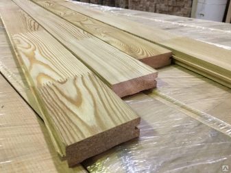
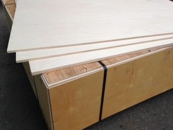
- For the manufacture of the machine body for wood, a solid wood board, MDF or chipboard profile sheet or plywood is suitable. The latter, along with solid wood, has the greatest strength. But for a metal machine, there is no better design than steel.
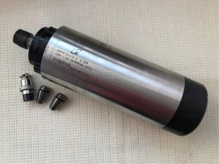
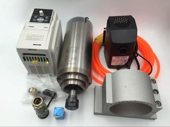
- The spindle motor for wood should not be more than 2 kW in power. To prevent protracted technological breaks every 15 minutes, it is advisable to equip the spindle motor with a radiator-water heat removal system.
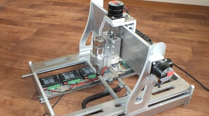
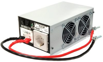
- The inverter electrical module is matched to the motor power. Due to the reliability and ubiquity of stepper motors, the "motor-driver" system is used. The driver board generates pulsed or alternating currents that cause the motor shaft to rotate at a specific angle or to complete several full revolutions. Three stepper motors provide movement of workpieces along all three coordinate axes.
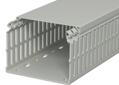
- The cable duct is placed to protect the wiring from accidental damage during operation - the drive and the stage are often moved a lot.
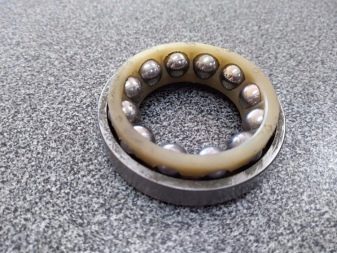
Other components include a milling clamp (cutter chuck), a cooling hose, ball bearing kits, a coupling (transfers a smooth ride from a stepper motor and ensures its alignment with a gearbox along the axis), milling cutters, hardware, a water pump (pump), studs. As tools you need:
-
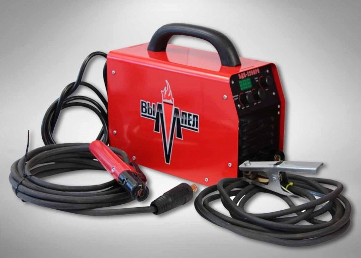
inverter-type welding unit with a number of electrodes;
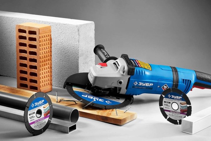
- grinder with a set of cutting discs for metal and wood;
-
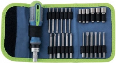
universal screwdriver with a set of nozzles;
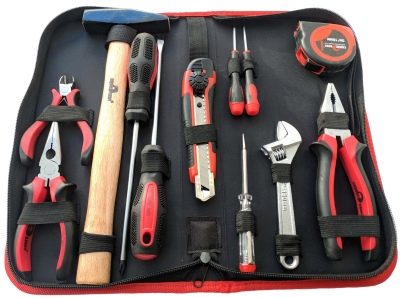
- hammer, pliers, universal adjustable wrenches (at least two);
-
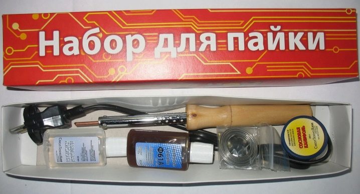
soldering iron, rosin, solder, soldering flux;
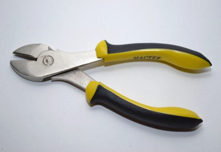
- Scissors and nippers.
Consumables - electrical tape, universal glue (carpentry, epoxy and / or "Moment-1"), rubber sealant, fum tape.


Craftsmen make milling cutters based on CDs and drives for them. Using these components, the user will receive a very compact machine.
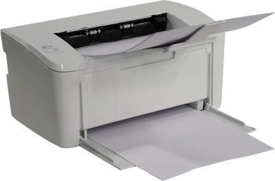
A better basis for the other option is an old branded printer from well-known manufacturers, for example, the HP LaserJet, which peaked in 2005.
The general step-by-step assembly instructions include the following stages.
-
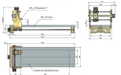
Search or create a drawing - assembly instructions, where all stages, including the layout of electrical and electronics, are described in detail. To create a drawing, software tools such as Autocad or Visio are used.
-
After purchasing the necessary components, the master forms the bed. It is not recommended to assemble it before purchasing these spare parts - its dimensions do not match the configuration of the future device.
-
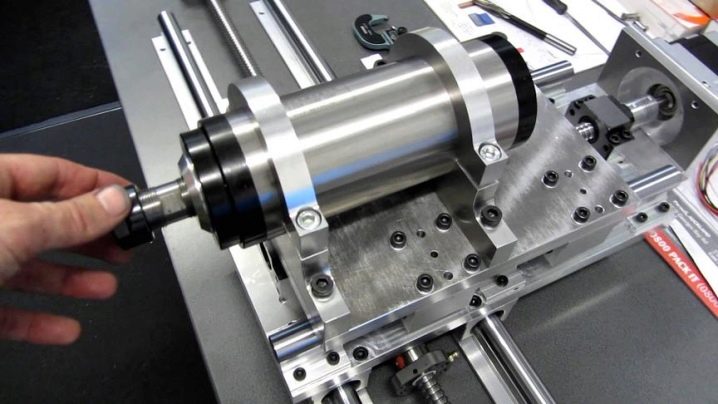
Installation and adjustment of the spindle unit with the main motor. A cooling system is installed on the engine. To eliminate leaks, a sealant is used - after hardening, it turns into a kind of rubber.
-
Installation of electrical wiring and cables, control panel, emergency shutdown button of the machine.
-
Placement and connection of the electronic board (microcontroller). You can use, for example, an electronic module like KY-2012 - a five-axis CNC controller for a stepper motor driver with a DB-25 cable. Most users prefer Arduino brand microcontrollers.
-
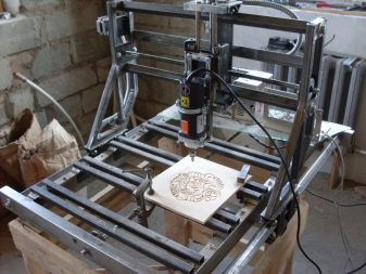
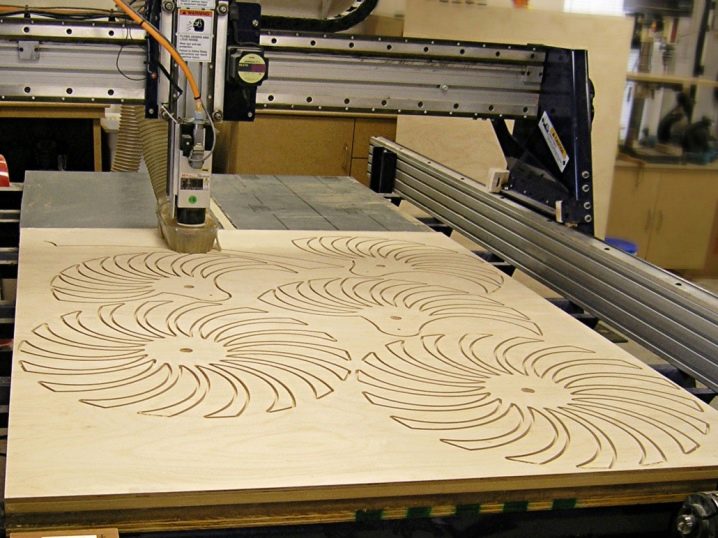
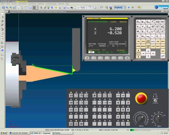
Testing the work of the assembled machine, downloading electronic versions of drawings of future workpieces, which will be made on this machine.
If the technique works well, then you can develop a production plan, purchase materials and consumables for it and go “on stream” - to release the first (trial) batch of parts.
Assembly technology
A self-assembled CNC machine requires a minimum of errors and unwanted miscalculations. A self-made unit, even when it was created for work exclusively on wood and plastic, requires a thorough approach to design and assembly. So, the project is ready - all that remains is to put it into practice.
Important nodes
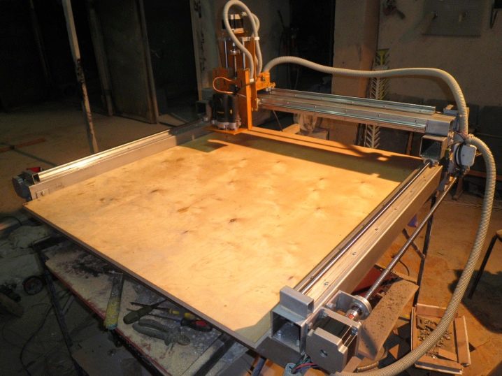
The bed, the power supply circuit, the drive with the main motor, and the object table with stepper motors in operation should not interfere with each other. No less important components are the emergency stop button and the remote control with buttons that switch the spindle drive speed.
Install the parts that allow you to adjust the displacement of the stage along the abscissa and ordinate axes.
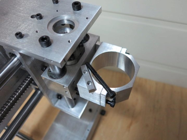
Mount the spindle. It is installed only after complete completion of work on the body (without assembling the sidewalls and rear wall). When installing the motor, leave the opportunity to move this drive in height and strictly vertically.
If the spindle drive is not mounted vertically, an additional structural element will be required that would allow the machine operator to set the desired angle of inclination of the cutter (or make sure that the spindle is aligned strictly vertically).
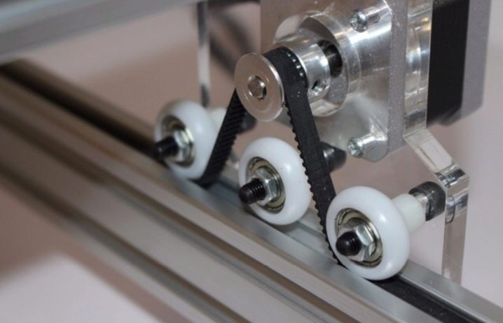
Other components include a helical gear using gears on the pulleys and belt... This connection prevents the belt from slipping on the pulleys. Uniform transmission of torque is virtually guaranteed.
When using a stepper motor for a miniature machine, carriage components from a large printer are used. The older the model is in the year of production, the more powerful the stepper motor was used in them. A dot matrix printer is considered a great success: it is more than laser and inkjet models, suitable for alteration for such a machine. A three-axis machine will require, respectively, three of these motors. If you could not find them on your own (using old printing equipment), then use stepper motors from the Chinese brand Nema - you just need to wait for the order to be delivered from 10 to 100 days, and such motors are designed for a voltage of 12 volts and a current of up to several amperes.
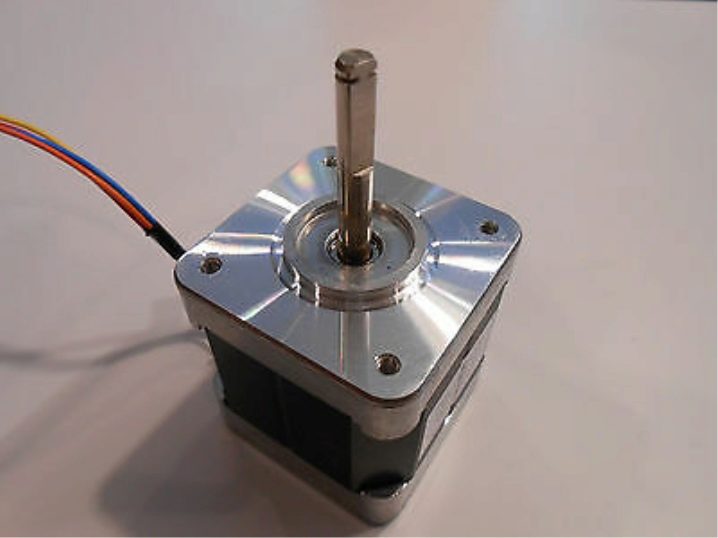
The preferred engines here are two- or three-reel models. Each of the motors will need its own controller (driver).
Using rotating gears (tool steel wheels), you can convert the torque into linear torque. Ball screw paired parts (Ball Screws) can be used for maximum accuracy, but such parts are not a cheap solution. Using nuts and mounting bolts to install the blocks, provide them with plastic spacers to reduce friction and reduce backlash.
Any brushed or brushless motor can be used for the spindle.
The vertical hub, which allows the tool to move in three coordinates, operates within the coordinate table. The axis is made in the form of an aluminum rod. The dimensions of this part must correspond to the dimensions of the machine.
If the master has a muffle furnace, then this axis can be made by himself only according to the drawing data.
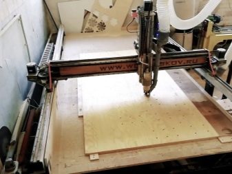
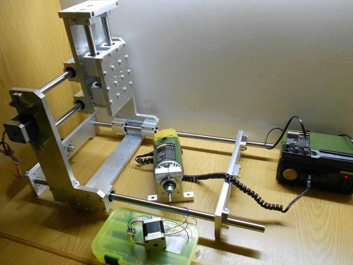
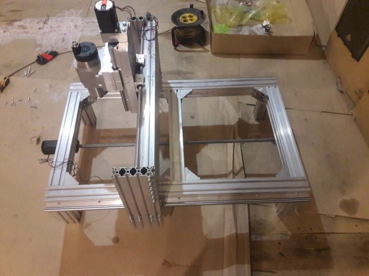
The assembly of the working mechanical part begins with the fastening of the first stepper motors to the frame.... They are located behind the vertical axis. These motors are responsible for horizontal and vertical movement. The mobile portal, moving along the abscissa axis, carries the spindle drive and the support (the axis that sets the height of the work point). The higher the portal is placed, the more thick parts the master reckons on when turning. The disadvantage of a raised portal is instability to increased applied force.
To secure the stepper motor, which is responsible for the height coordinates, as well as the straight rails, use all plates except the side plates. Install the spindle base in the same place.
Use pre-selected studs with nuts for the drive.
To fix the rotor of the spindle motor with a hairpin, use a rubber winding of an electric cable with a rather wide cross-section. Screws inserted into the nylon sleeve also have locking properties.
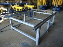
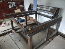
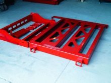
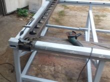
Stanina
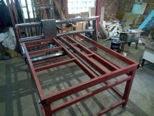
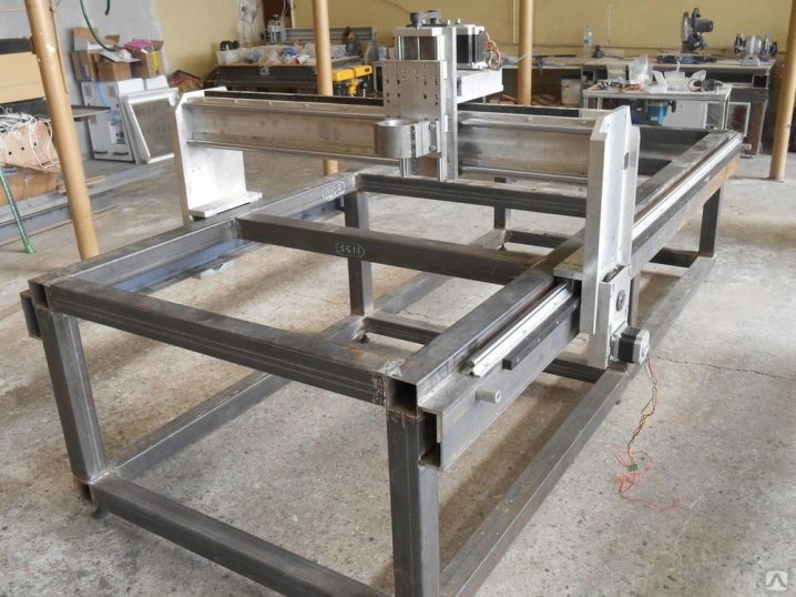
Metals and wood in the manufacture of the case can be combined with each other. So, the main (supporting) structure is assembled from professional pipes with a wall thickness of 3 mm, and the sidewalls (covers, panels) can be made of plywood. But the supporting frame cannot be assembled without welding technology - purely bolted connections may not be enough.
The machine acquires the ultimate strength declared in the drawing only thanks to the frame... A movable object table, a spindle drive, stepping coordinate motors, rail-like guides, and a vertical coordinate axis are installed on it.
The welded frame, formed from aluminum profiles and rods, does not carry loads well.
A steel frame is many times better, but it can also be damaged prematurely. Use T-nuts to prevent frame parts from pulling apart. However, bolted connections go well with welded connections. The end plates provide for the installation of bearings that allow the lead bolt to rotate freely along its thread. Here slide and bearing on the spindle are used.
Electronic filling
For the smooth operation of the program unit, high-quality radio materials and radio components are used. Chinese printed circuit boards of dubious quality should be avoided. The purpose of the assembly is to achieve accurate functioning, without software freezes and resets during operation.
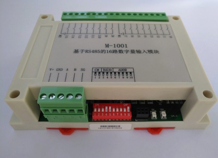
In addition to stepper motors controlled by electronic driver modules, a USB port is also used, the conversion of signals from which, for example, is performed using an adapter module based on RS-485 technology, which also converts data back into USB format.
All electronics are powered most often with the help of a computer power supply with step-output voltages, for example: 3.3, 5, 6, 9, 12, 15, 18, 19, 21, 24, 27, 30 and 36 volts.
Select the one you need - all the equipment works on it. For example, modern microprocessor modules operate at 3.3 V, and stepper motors - from 12.
A PC or laptop is used to load / overwrite the program to the CNC unit. Recently, attempts have been made to use an additional microcomputer the size of one or more flash drives to control the machine, interacting with smartphones and tablets via Wi-Fi or Bluetooth, but this technology is still in the stage of long-term development and, rather, refers to “smart things”.
Possible mistakes
- Not a single sane craftsman will assemble even an extremely simple machine without a project with a drawing.
- Correctly match the spindle drive and frequency converter.
- Do not use stepper motors with a non-standard power supply, otherwise you will need to install a non-standard power source or modify one of the existing ones. This will push the final setting aside, complicate it.
- Do not use only welded joints - with extreme vibration, they will simply break.
- Do not use a sliding belt drive: the appreciable force can lead to frequent slipping of the belts.
- Purchase bearings and screws with a triple safety factor.
How to make a CNC machine with your own hands, see below.


The comment was sent successfully.