ATS for a generator: features and connection
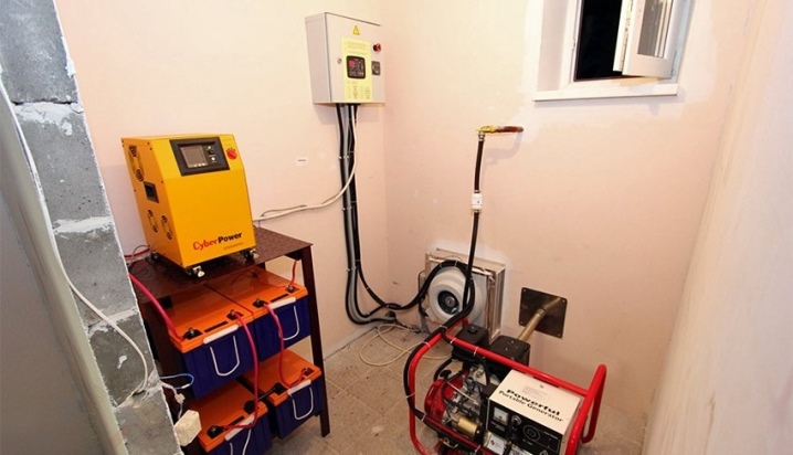
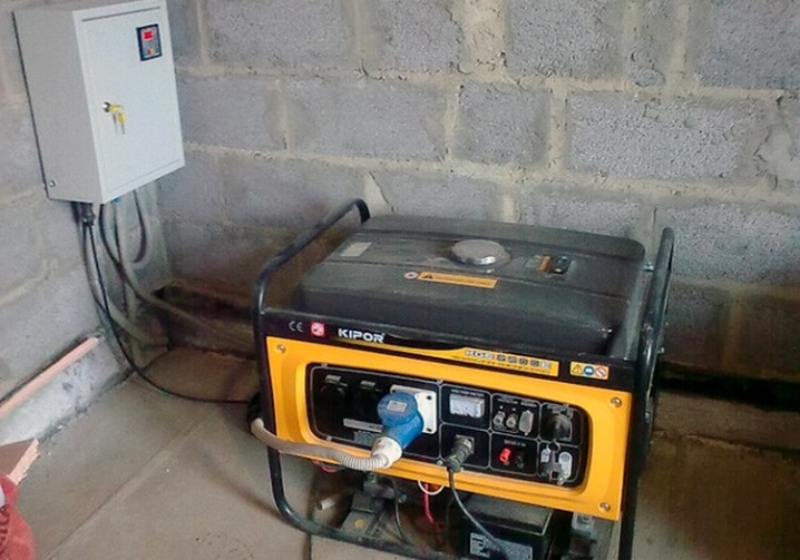
Alternative energy sources are becoming more and more widespread these days, since they allow providing uninterrupted power supply to objects of various directions. First of all, cottages, summer cottages, small buildings, where there are power outages.
If the usual power supply disappears, then there is a need to turn on the backup power source as soon as possible, which is not always possible for various reasons. It is for these purposes that automatic switching on of a reserve or ATS for the generator. This solution makes it possible in a matter of seconds, activate the backup power without much difficulty.
What it is?
As mentioned above, ATS is translated as automatic switching on (input) of the reserve. The latter should be understood as any generator that generates electricity if the facility is no longer supplied with power.
This device is a kind of load switch that does this at the moment of need. A number of ATS models require manual adjustment, but most are controlled in auto mode by a voltage loss signal.
It should be said that this block consists of a number of nodes and is either single-phase or three-phase. To change the load, you just need to install a special controller after the electric meter. The position of the power contacts will be controlled by the main source of electrical energy.
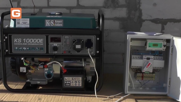
Almost all types of devices with a start from an electrical station can be equipped with autonomous ATS mechanisms. A special ATS cabinet should be used to install redundant injection units. At the same time, the ATS switchboard is usually placed either after the gas generators, or installed on a common electrical panel.
Types and their structure
It should be said that the types of ATS devices can differ according to the following criteria:
- by voltage category;
- by the number of spare sections;
- switching delay time;
- network power;
- by the type of a spare network, that is, used in a single-phase or three-phase network.
But most often, these devices are divided into categories according to the connection method. In this case, they are:
- with automatic switches;
- thyristor;
- with contactors.
Talking about models with automatic knife switches, then the main working element of such a model will be a switch with an average zero position. To switch it, a motor-type electric drive is used under the control of the controller. Such a shield is very easy to disassemble and repair in parts. It is very reliable, but it has no short circuit and voltage surge protection. Yes, its cost is quite high.
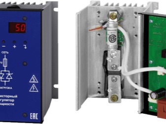
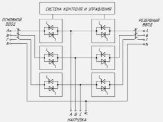
Thyristor models They differ in that here the switching element is high-power thyristors, which make it possible to connect the second input instead of the first, which is out of order, almost instantly.
This aspect will mean a lot when choosing an ATS for those who care about having electricity at all times, and any, even the smallest, failure can cause some serious problems.
The cost of this type of ATS is high, but sometimes the other option simply cannot be used.
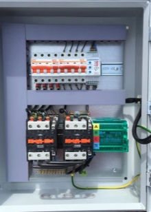
Another type is with contactors. It is the most common today. This is due to affordability.Its main parts are 2 interlocking contactors, electromechanical or electrical, as well as a relay that is designed to control the phases.
The most affordable models control only one phase, without taking into account the voltage quality. When the voltage supply to one phase is cut off, the load is automatically transferred to the other power supply.
More expensive models provide the ability to control frequency, voltage, time delays and program them. In addition, it is possible to perform mechanical blocking of all inputs at the same time.
But if the devices fail, it cannot be blocked manually. And if you need to repair one element, you will have to repair the entire unit at once.
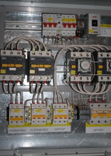
Speaking about the design of the ATS, it should be said that it consists of 3 nodes, which are interconnected:
- contactors that switch input and load circuits;
- logical and indication blocks;
- relay switching unit.
Sometimes they can be equipped with additional nodes to eliminate voltage dips, time delays, and improve the quality of the output current.
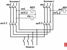
The inclusion of a spare line allows the group of contacts to be provided. The presence of the incoming voltage is monitored by a phase monitoring relay.
If we talk about the principle of work, then in standard mode, when everything is powered from the mains, the contactor box directs electricity to the consumer lines thanks to the presence of an inverter.
The signal about the presence of voltage of the input type is supplied to the devices of the logical and indication type. In normal operation, everything will work steadily. If an emergency occurs in the main network, the phase control relay ceases to keep the contacts closed and they open, with the subsequent deactivation of the load.
If there is an inverter, then it turns on to generate an alternating current with a voltage of 220 volts. That is, users will have a stable voltage if there is no voltage in the normal network.
If the mains operation is not restored when necessary, the controller signals this with the generator start. If there is a stable voltage from the alternator, then the contactors are switched to the spare line.
Automatic switching on of the consumer's network begins with the supply of voltage to the phase-control relay, which switches the contactors to the main line. The spare power circuit is opened. The signal from the controller goes to the fuel supply mechanism, which closes the gas engine flap, or shuts off the fuel in the corresponding engine block. After that, the power plant is shut down.
If there is a system with autostart, then human participation is not required at all. The whole mechanism will be reliably protected from the interaction of opposite currents and short circuits. For this, a locking mechanism and various additional relays are usually used.
If required, the operator can use the manual line switching mechanism with the help of the controller. He can also change the settings of the control unit, activate automatic or manual operating mode.
Secrets of choice
Let's start with the fact that there are some "chips" that allow you to choose a really high-quality ATS, and it does not matter for which mechanism - for three-phase or single-phase. The first point is that contactors are extremely important, their role in this system is difficult to overestimate. They must be very sensitive and track literally the smallest change in the parameters of the input stationary network.
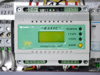
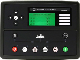
The second important point, which cannot be ignored, is controller... In fact, this is the brain of the AVP unit.
It is best to buy Basic or DeepSea models.
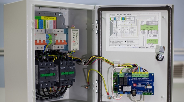
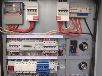
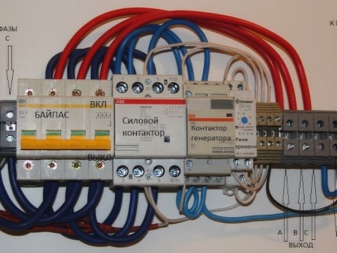
Another subtlety is that a correctly executed shield on the panel must have certain mandatory attributes. These include:
- emergency shutdown button;
- measuring devices - a voltmeter that allows you to control the voltage level and ammeter;
- light indication, which makes it possible to understand whether the power is from the mains or from the generator;
- switch for manual control.
An equally important aspect will be the fact that if the tracking part of the ATS unit is mounted on the street, then the box must have a degree of protection against moisture and dust of at least IP44 and IP65.
In addition, all terminals, cables and clamps inside the box must be marked as indicated in the diagram. Together with the operating instructions, it must be understandable.
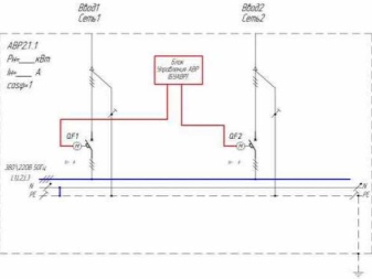
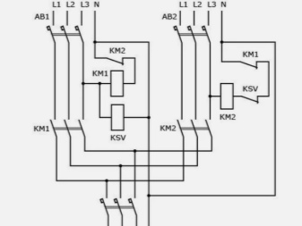
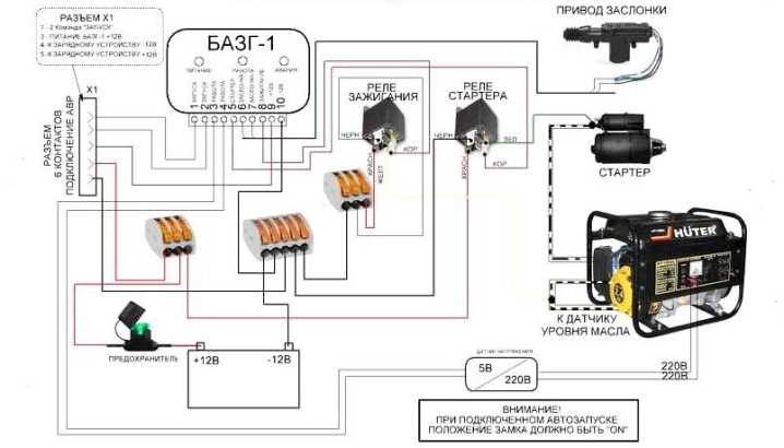
Connection diagrams
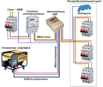
Now let's try to figure out how to properly connect the ATS. Usually there is a scheme for 2 inputs.
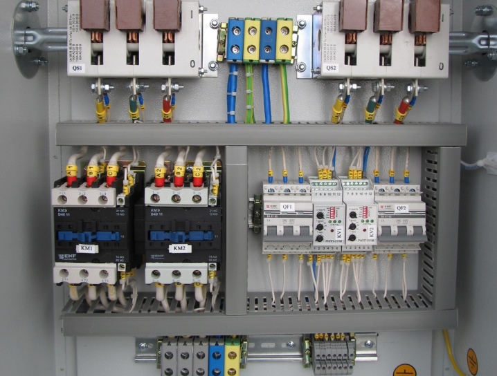
First, you should make the correct placement of the elements in the electrical panel. They should be mounted so that no wire crossings are observed. The user must have full access to everything.
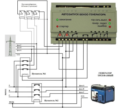
And only then can the power blocks of the automatic transfer switch with controllers be connected according to the basic wiring diagram. Its commutation with controllers is done using contactors. After that, a connection is made to the ATS generator. The quality of all connections, their correctness, can be checked using an ordinary multimeter.
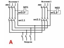
If the mode of receiving voltage from a standard power transmission line is used, then the generator automation is activated in the ATS mechanism, the first magnetoplayer is turned on, supplying voltage to the shield.
If an emergency occurs and the voltage disappears, then using the relay, magnetic starter No. 1 is deactivated and the generator receives a command to carry out autostart. When the generator starts to work, the magnetic starter number 2 is activated in the ATS panel, through which the voltage goes to the distribution box of the home network. So everything will work either until the power supply is restored on the main line, or when the fuel in the generator runs out.
When the main voltage is restored, the generator and the second magnetic starter are turned off, giving a signal to the first to start, after which the system goes to standard operation.
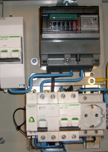
It should be said that the installation of the ATS switchboard must be carried out after the electric meter.
That is, it turns out that during the operation of the generator, electricity is not counted, which is logical, because the power is not supplied from a centralized source of power supply.
The ATS panel is mounted before the main panel of the home network. Therefore, it turns out that according to the scheme, it must be mounted between the electric energy meter and the junction box.
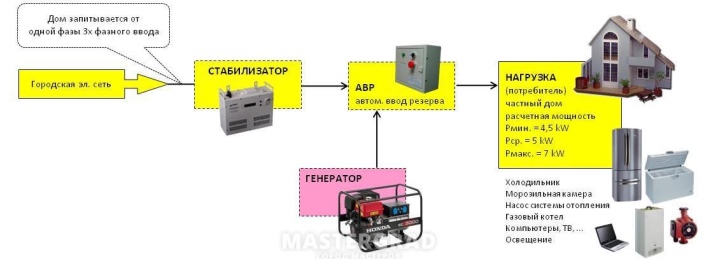
If the total power of consumers is more than what the generator can give or the device itself does not have a lot of power, only those devices and equipment should be connected to the line that are exactly required to ensure the normal life of the facility.
From the next video you will learn about the simplest schemes for constructing ATS, as well as ATS circuits for two inputs and a generator.


The comment was sent successfully.