How to make a parallel stop for a circular saw with your own hands?

The rip fence is an important tool when working with a circular saw. This device is used to make cuts parallel to the plane of the saw blade and the edge of the material being processed. Usually, one of the options for this device is supplied by the manufacturer with the circular saw. However, the manufacturer's version is not always convenient to use and in most cases does not meet the needs of the consumer. Therefore, in practice, you have to do one of the options for this device with your own hands according to simple drawings.
There are several options for a constructive solution to this seemingly simple task. All options have their own advantages and disadvantages. The choice of a suitable design should be based on the needs that arise when processing various materials on a circular saw. Therefore, choosing the right solution must be taken seriously, responsibly and creatively.
This article discusses two of the simplest design solutions for creating an angular parallel stop for a circular saw with your own hands according to the existing drawings.

Peculiarities
Common to these design solutions is a rail that moves relative to the cutting disc along the plane of the saw table. When creating this rail, it is proposed to use a typical extruded profile of a rectangular unequally flange angular section of aluminum or magnesium alloys. When assembling a parallel corner stop with your own hands, you can use other profiles of a similar section in accordance with the length and width of the working plane of the table, as well as the mark of the circular.
In the proposed options for drawings, an angle with the following dimensions (mm) is used:
- wide - 70x6;
- narrow - 41x10.


Execution first
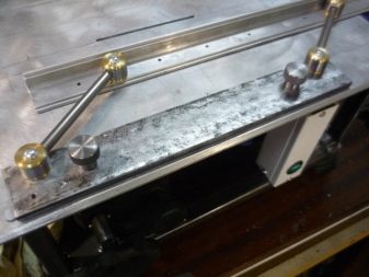
A rail is taken from the above-mentioned corner with a length of 450 mm. For correct marking, this workpiece is placed on the working table of the circular so that the wide bar is parallel to the saw blade. The narrow strip should be on the opposite side of the drive from the work table, as shown in the figure. In a narrow shelf (41 mm wide) of the corner at a distance of 20 mm from the end, the centers of three through holes with a diameter of 8 mm are marked, the distances between them should be the same. From the line of location of the marked centers, at a distance of 268 mm, the line of the location of the centers of three more through holes with a diameter of 8 mm (with the same distance between them) is marked. This completes the markup.


After that, you can proceed directly to the assembly.
- 6 marked holes with a diameter of 8 mm are drilled, the burrs inevitably created during drilling are processed with a file or emery paper.
- Two pins 8x18 mm are pressed into the extreme holes of each triplet.
- The resulting structure is placed on the working table in such a way that the pins enter the grooves provided for by the design of the circular saw table, on both sides of the saw blade perpendicular to its plane, the narrow angle bar is located on the plane of the working table. The entire device moves freely along the surface of the table parallel to the plane of the saw blade, the pins act as guides, prevent skewing of the stop and violation of the parallelism of the planes of the circular disk and the vertical surface of the stop.
- From the bottom of the desktop, M8 bolts are inserted into the grooves and middle holes between the pins of the stop so that their threaded part goes into the slot of the table and the holes of the rail, and the bolt heads rested against the bottom surface of the table and ended up between the pins.
- On each side, over the rail, which is a parallel stop, a wing nut or ordinary M8 nut is screwed onto the M8 bolt. Thus, a rigid attachment of the entire structure to the work table is achieved.


Operating procedure:
- both wing nuts are released;
- the rail moves to the required distance from the disc;
- fix the rail with nuts.

The rail moves parallel to the working disc, since the pins, acting as guides, prevent the parallel stop from skewing relative to the saw blade.
This design can only be used if there are grooves (slots) on both sides of the blade perpendicular to its plane on the circular saw table.
Second constructive solution
The do-it-yourself design of a parallel stop for a circular saw offered below is suitable for any work table: with or without grooves on it. The dimensions suggested in the drawings refer to a certain type of circular saws, can be proportionally changed depending on the parameters of the table and the brand of the circular.


A rail with a length of 700 mm is prepared from the corner indicated at the beginning of the article. At both ends of the corner, at the ends, two holes are drilled for the M5 thread. A thread is cut in each hole with a special tool (tap).
According to the drawing below, two rails are made of metal. For this, a steel equal-flange corner with a size of 20x20 mm is taken. Turned and cut according to the dimensions of the drawing. On the larger bar of each guide, two holes with a diameter of 5 mm are marked and drilled: in the upper part of the guides and one more in the middle of the lower one for the M5 thread. A thread is tapped into the threaded holes with a tap.
The guides are ready, and they are attached to both ends with M5x25 socket head bolts or standard M5x25 hex head bolts. Screws M5x25 with any head are screwed into the holes of the threaded guides.


Operating procedure:
- the screws are loosened in the threaded holes of the end guides;
- the rail moves from the corner to the cut size required for work;
- the selected position is fixed by tightening the screws in the threaded holes of the end guides.
The movement of the stop bar occurs along the end planes of the table, perpendicular to the plane of the saw blade. Guides at the ends of the parallel stop angle allow you to move it without distortions relative to the saw blade.


For visual control of the position of the homemade parallel stop, a marking is drawn on the plane of the circular table.
For information on how to make a parallel emphasis for a homemade circular table, see the next video.


The comment was sent successfully.